Fineblanking Press
ProductOverview
Fineblanking is a precision shearing process that produces flat parts with a fully sheared, smooth edge across the entire material thickness in a single stroke. A conventional blanked edge has a small burnished band and a large torn fracture zone; a fineblanked edge is clean and square over 70 to 100 percent of the thickness, often good enough to use as a functional surface without machining. The process makes this possible by combining three things: a very stiff press, a tiny punch-die clearance, and a Vee-Ring Clamping System that clamps the material so it flows in compression rather than tearing.
A Fineblanking Press therefore differs from an ordinary stamping press in that it applies three independently controlled forces at once: the main cutting force from the Main Cutting Drive, the clamping force from the vee ring, and the counter-pressure from the Counterforce System holding the part flat against the punch. The whole stroke runs slowly so the material has time to flow. Around those forces sit a rigid Closed Frame Structure, the Triple-Action Tooling, a Strip Feed System for coil stock, and a CNC Control System.
Frame and Stiffness
Edge quality in fineblanking is extremely sensitive to deflection. If the frame opens even slightly under load, the punch tips, the clearance changes around the cut, and the smooth band breaks up into fracture. For that reason the Frame Casting is a closed (O-type) frame with very high bending stiffness, not the open C-frame used on a Hydraulic Punch Press. The Cutting Slide runs in preloaded zero-backlash Preloaded Slide Guide members, and both the slide face and the Bed Plate are ground flat to a few microns. The goal is to keep the punch and die parallel within microns through the entire stroke.
The Three Forces
The first force is cutting. The Main Cutting Cylinder drives the Cutting Slide down at a controlled 5 to 15 mm/s, slow enough that the metal shears by plastic flow. A Slide Position Sensor and a Cutting Force Sensor feed the control loop.
The second force is clamping, supplied by the Vee-Ring Clamping System. Just before the cut, a Clamping Cylinder presses the Vee-Ring Plate into the strip so that its sharp vee-shaped ring, the stinger, bites into the material just outside the cut line. This puts the cut zone into compression and prevents the crack that would otherwise run ahead of the punch. The vee ring is the single feature that distinguishes fineblanking from all other shearing.
The third force is counter-pressure. The Counter-Pressure Cylinder pushes up against the underside of the part during the cut, keeping it flat and supported. After the cut, that same cylinder drives the Ejector Pin to lift the finished blank out of the die, and an Air Blow-Off nozzle clears it away.
Tooling
The Triple-Action Tooling carries the geometry that makes the process work. The Blanking Punch and Die Plate are set with a punch-die clearance of roughly 0.5 percent of the sheet thickness, about a tenth of conventional clearance, which is what forces the smooth full-thickness cut. Both are made from powder-metallurgy tool steel hardened to 60 to 62 HRC because the tight clearance and high pressure are abrasive. A Vee-Ring Insert forms the vee impression and is replaceable as it wears. Punch, die and vee plate are kept concentric to a few microns by Tool Guide Pin members running in Ball Bearing bushings.
Strip Feed
Parts are blanked from coil. The Strip Feed System uses a Coil Straightener to remove coil set, since flat stock is essential, then a Servo Motor drives a pair of Feed Roll grippers to advance the strip by exactly one part pitch. Before the slide closes, a Strip Pilot registers the strip precisely in the die, correcting any small feed error so that hole patterns and the outer profile stay in register part to part.
Hydraulics and Control
The Hydraulic Unit supplies up to 320 bar from a High-Pressure Pump driven by a 30 to 75 kW Pump Motor, and meters each of the three forces through its own Proportional Valve. Independent metering is what lets the operator tune the cutting, clamping and counter forces separately for a given material and thickness. The Control System runs on a CNC Controller that profiles slide position and the three force curves for every stroke and coordinates the feed. The operator sets up and monitors jobs from the HMI Panel. Guarding through the Safety System combines an interlocked Die Guard with a Safety Light Curtain over the feed zones, all routed through a Safety Relay.
Variants and Use
Fineblanking presses are sized by cutting force, from about 160 tons for small parts up to 1,000 tons for thick automotive components. They are the standard way to make flat parts that need accurate, smooth edges in volume: spur and segment gears, seat recliner mechanisms, brake and clutch plates, lever arms, and chain links. The payoff is the elimination of secondary machining, since the sheared edge is already square and smooth, and the high part-to-part consistency that comes from the slow, force-controlled stroke. Compared with a Mechanical Power Press or a Hydraulic Punch Press, a fineblanking press is slower and more costly to tool, but it is the only single-operation process that yields a finished, full-thickness edge.
Fineblanking Press parts and their functions
9 top-level parts · 244 parts in total · full bill of materials below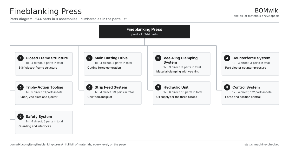
| # | Part | Qty | What it does |
|---|---|---|---|
| 1 | Closed Frame Structure 4 parts | 1× | Stiff closed-frame structure |
| 2 | Main Cutting Drive 4 parts | 1× | Cutting force generation |
| 3 | Vee-Ring Clamping System 3 parts | 1× | Material clamping with vee ring |
| 4 | Counterforce System 3 parts | 1× | Part ejector counter-pressure |
| 5 | Triple-Action Tooling 5 parts | 1× | Punch, vee plate and ejector |
| 6 | Strip Feed System 4 parts | 1× | Coil feed and pilot |
| 7 | Hydraulic Unit 6 parts | 1× | Oil supply for the three forces |
| 8 | Control System 4 parts | 1× | Force and position control |
| 9 | Safety System 4 parts | 1× | Guarding and interlocks |
3D model
No 3D model yet. Have a CAD file of this? Add a 3D model — STL renders right on this page; STEP, FreeCAD, and OpenSCAD sources are welcome too (openly licensed, like all 3D models on BOMwiki).
Build & assembly graph
expand / collapse · shared sub-assemblies converge · links to related products · est. labourTap an assembly to expand/collapse · tap a part to open it · use “Open page” for any node · drag to pan, scroll to zoom.
Bill of materials for Fineblanking Press
9 top-level lines · 54 rows shown · 244 parts total · indented to 3 levels| # | Item / sub-assembly | Part no. | Qty/assy | Ext. qty | Parts | Type |
|---|---|---|---|---|---|---|
| 1 | Closed Frame Structure 4 parts | fbp-frame | 1× | 1 | 7 | assembly |
| 1.1 | Frame Casting | fbp-frame-casting | 1× | 1 | · | part |
| 1.2 | Preloaded Slide Guide | fbp-slide-guide | 4× | 4 | · | part |
| 1.3 | Bed Plate | fbp-bed-plate | 1× | 1 | · | part |
| 1.4 | Fastener Set | fastener-set | 1× | 1 | · | part |
| 2 | Main Cutting Drive 4 parts | fbp-main-drive | 1× | 1 | 4 | assembly |
| 2.1 | Main Cutting Cylinder | fbp-main-cylinder | 1× | 1 | · | part |
| 2.2 | Cutting Slide | fbp-slide | 1× | 1 | · | part |
| 2.3 | Slide Position Sensor | fbp-position-sensor | 1× | 1 | · | part |
| 2.4 | Cutting Force Sensor | fbp-force-sensor | 1× | 1 | · | part |
| 3 | Vee-Ring Clamping System 3 parts | fbp-vee-ring-system | 1× | 1 | 3 | assembly |
| 3.1 | Vee-Ring Plate | fbp-vee-ring-plate | 1× | 1 | · | part |
| 3.2 | Clamping Cylinder | fbp-clamp-cylinder | 1× | 1 | · | part |
| 3.3 | Guide Plate | fbp-guide-plate | 1× | 1 | · | part |
| 4 | Counterforce System 3 parts | fbp-counterforce-system | 1× | 1 | 3 | assembly |
| 4.1 | Counter-Pressure Cylinder | fbp-counter-cylinder | 1× | 1 | · | part |
| 4.2 | Ejector Pin | fbp-ejector-pin | 1× | 1 | · | part |
| 4.3 | Air Blow-Off | fbp-air-blow | 1× | 1 | · | part |
| 5 | Triple-Action Tooling 5 parts | fbp-triple-action-tooling | 1× | 1 | 11 | assembly |
| 5.1 | Blanking Punch | fbp-punch | 1× | 1 | · | part |
| 5.2 | Die Plate | fbp-die-plate | 1× | 1 | · | part |
| 5.3 | Vee-Ring Insert | fbp-vee-insert | 1× | 1 | · | part |
| 5.4 | Tool Guide Pin | fbp-tool-guide-pin | 4× | 4 | · | part |
| 5.5 | Ball Bearing | ball-bearing | 4× | 4 | · | part |
| 6 | Strip Feed System 4 parts | fbp-strip-feed | 1× | 1 | 29 | assembly |
| 6.1 | Feed Roll | fbp-feed-roll | 2× | 2 | · | part |
| 6.2 | Servo Motor 4 parts | servo-motor | 1× | 1 | 24 | assembly |
| 6.2.1 | Stator Assembly 3 parts + deeper › | stator-assembly | 1× | 1 | 3 | assembly |
| 6.2.2 | Rotor Assembly 4 parts + deeper › | rotor-assembly | 1× | 1 | 19 | assembly |
| 6.2.3 | Encoder | encoder | 1× | 1 | · | part |
| 6.2.4 | Motor Housing | motor-housing | 1× | 1 | · | part |
| 6.3 | Strip Pilot | fbp-pilot | 2× | 2 | · | part |
| 6.4 | Coil Straightener | fbp-straightener | 1× | 1 | · | part |
| 7 | Hydraulic Unit 6 parts | fbp-hydraulic-unit | 1× | 1 | 10 | assembly |
| 7.1 | High-Pressure Pump | fbp-pump | 1× | 1 | · | part |
| 7.2 | Pump Motor | fbp-pump-motor | 1× | 1 | · | part |
| 7.3 | Oil Reservoir | fbp-reservoir | 1× | 1 | · | part |
| 7.4 | Proportional Valve | fbp-proportional-valve | 3× | 3 | · | part |
| 7.5 | Return Line Filter | return-filter | 1× | 1 | · | part |
| 7.6 | Pressure Sensor | pressure-sensor | 3× | 3 | · | part |
| 8 | Control System 4 parts | fbp-control-system | 1× | 1 | 172 | assembly |
| 8.1 | CNC Controller 4 parts | fbp-cnc-controller | 1× | 1 | 169 | assembly |
| 8.1.1 | Bare PCB | pcb-bare | 1× | 1 | · | part |
| 8.1.2 | Microcontroller | mcu | 2× | 2 | · | part |
| 8.1.3 | Relay | relay | 6× | 6 | · | part |
| 8.1.4 | SMD Passive (R/C/L) | smd-passives | 160× | 160 | · | part |
| 8.2 | HMI Panel | hmi-panel | 1× | 1 | · | part |
| 8.3 | Power Supply | power-supply | 1× | 1 | · | part |
| 8.4 | Wire Bundle | wire-bundle | 1× | 1 | · | part |
| 9 | Safety System 4 parts | fbp-safety-system | 1× | 1 | 5 | assembly |
| 9.1 | Die Guard | fbp-die-guard | 1× | 1 | · | part |
| 9.2 | Safety Light Curtain | fbp-light-curtain | 1× | 1 | · | part |
| 9.3 | E-Stop | fbp-estop | 2× | 2 | · | part |
| 9.4 | Safety Relay | fbp-safety-relay | 1× | 1 | · | part |
Related products
same domain, ranked by shared parts CNC Lathe
511 parts · shares 2 with this page
CNC Lathe
511 parts · shares 2 with this page
 CNC Milling Machine
400 parts · shares 2 with this page
Gear Honing Machine
260 parts · shares 2 with this page
Gear Shaving Machine
240 parts · shares 1 with this page
Keyway Broaching Machine
179 parts · shares 1 with this page
CNC Milling Machine
400 parts · shares 2 with this page
Gear Honing Machine
260 parts · shares 2 with this page
Gear Shaving Machine
240 parts · shares 1 with this page
Keyway Broaching Machine
179 parts · shares 1 with this page
Sourcing: possible vendors
Prices, MOQ, and lead times are algorithmic estimates, not quotes, and not claims about these companies. Company mappings are curated by keyword; est. price band $10k–$1M. How estimates work| Vendor | HQ | Specialty | MOQ | Lead time |
|---|---|---|---|---|
|
🇩🇪DMG MORI
dmgmori.com ↗
|
Bielefeld, DE | Machine tools | 5 units | 12–20 wks |
|
🇯🇵Mazak
mazak.com ↗
|
Oguchi, JP | Machine tools | 5 units | 12–20 wks |
| haascnc.com ↗ | Oxnard, US | CNC machine tools | 5 units | 12–20 wks |
|
🇯🇵Okuma
okuma.com ↗
|
Niwa, JP | Machine tools | 5 units | 12–20 wks |
|
🇩🇪Trumpf
trumpf.com ↗
|
Ditzingen, DE | Laser & sheet-metal machines | 5 units | 12–20 wks |
927-word article