Internal Cylindrical Grinder
ProductOverview
An internal cylindrical grinder finishes the inside diameter of a part to final size, roundness, and surface finish after that part has been hardened. It is the bore counterpart to outside-diameter grinding, and it does the harder job: the wheel has to work inside a hole, so it can only be as large as the bore will accept, and on small bores that means a wheel of a few millimetres. The typical work is rings and sleeves that cannot be turned to finish because they are too hard or too precise, bearing inner and outer rings, gear bores, hydraulic spool and valve bores, fuel injector bodies, bushings, and die bores. Bore roundness of 0.3–1 µm and size held to a few microns are normal production results on a machine like this. The bore is ground concentric to a chosen reference, usually the part's own outside diameter or a face, and that concentricity is often more important than the absolute diameter because it controls how the assembled part runs.
How it works
The part is mounted in the Workhead and rotated at roughly 100 to 600 rpm. The Wheelhead and Quill carries a small mounted wheel on the end of a slender Wheel Quill that reaches into the bore. Because the wheel is small, it must spin extremely fast to reach a usable cutting speed: a 10 mm wheel needs around 60,000 rpm just to reach 30 m/s at its rim, so spindle speeds of 30,000 to 150,000 rpm are standard, and the Spindle Cartridge is the defining component of the machine. Many machines float that spindle on an Air-Bearing Sleeve because an air film gives near-zero runout and almost no heat at those speeds. The Infeed Slide feeds the wheel radially into the bore wall to set diameter, while the Table and Oscillation Slide reciprocates along the bore axis so the narrow wheel sweeps the full length on each stroke. That traverse motion is what makes the bore a true cylinder rather than just a ring ground at one plane, and the Oscillation Drive adds a fast dither over the traverse to spread wheel grain and keep the surface even.
Holding the part
How the part is held decides the concentricity of the finished bore. A simple Work Chuck grips the outside diameter, and the bore comes out concentric to that grip to within the chuck's accuracy. For thin rings that a chuck would distort, an Magnetic Face Plate holds the part flat by one face. The most accurate method for bearing rings is the Shoe Support: the ring rides on two carbide shoes that locate it on its own outside diameter while a backing roller drives it, so the bore is ground true to the OD without any gripping force at all. The Workhead Spindle runs in preloaded bearings because its own runout adds directly to the concentricity error of the part.
Wheels, wear, and dressing
Small wheels wear fast. A bore wheel removes stock with a tiny contact patch and a short rim, so it loses radius quickly and must be dressed far more often than the large wheel on an outside-diameter machine. That is why the Diamond Dressing Unit sits permanently on the machine and trues the wheel between parts, sometimes between passes. The Mounted Wheels and Quills holds a range of mounted wheels sized close to each bore. Vitrified aluminium-oxide Mounted Grinding Wheel stock is cheap and easy to dress but wears quickly on hardened steel, so production work has largely moved to the CBN Bore Wheel. Cubic boron nitride holds its form for thousands of bores, cuts cooler, and shifts the dressing job to a powered Rotary Dresser instead of a single-point diamond. The CNC Control tracks every dress, since each one removes wheel radius, and re-feeds the infeed slide so the finished diameter does not drift as the wheel shrinks.
Sizing and gauging
Because the wheel is constantly changing diameter, the machine cannot grind to size by slide position alone. It measures the bore as it grinds. The In-Process Gauging head enters the bore and reads diameter live, and the control stops the infeed exactly when the In-Process Bore Gauge reports finished size. The Gauge Fingers ride the bore wall and read to better than a micron, and a Gauge Retract swings the head clear during load and unload. After grinding, a Post-Process Gauge re-checks the bore and feeds a slow correction back so the process holds size across a long run. A Face Grinding Attachment attachment can grind the part face square to the bore in the same setup, which keeps bore-to-face squareness tight and removes a second handling step.
Materials and structure
The work is almost always hardened, in the range of 58 to 64 HRC, which is the reason for grinding rather than boring. Bearing rings are through-hardened chrome steel, gears are case-hardened alloy steel, and valve and injector bores are nitrided or hardened tool steels. The machine itself is built for stillness: the Bed and Structure is granite or grey iron of 1.5 to 6 t for damping, the Quill Balancing Ring cancels quill unbalance that would otherwise print chatter at high speed, and the slides run on hydrostatic or precision rolling guideways. Heat is the main enemy of bore size, so the Coolant System system pushes filtered, chilled coolant through a Coolant Nozzle into the buried contact deep inside the bore where access is tight, and a chiller holds it within about a degree so the part does not grow during the cycle.
Variants and use
Machines range from small manual bore grinders for toolroom work up to fully automated CNC cells that load rings from a feeder through the Loader Interface, grind bore and face, gauge, and sort in a few seconds per part. Bearing plants run banks of these machines as the finishing step on inner and outer ring bores. Universal grinders combine internal and external grinding on one bed for low-volume precision work where both diameters must be concentric. Across all of them the constraints are the same: a small fast wheel, a slender quill that limits how deep and stiff the grind can be, frequent dressing, and live gauging to hold size as the wheel wears away.
Internal Cylindrical Grinder parts and their functions
10 top-level parts · 176 parts in total · full bill of materials below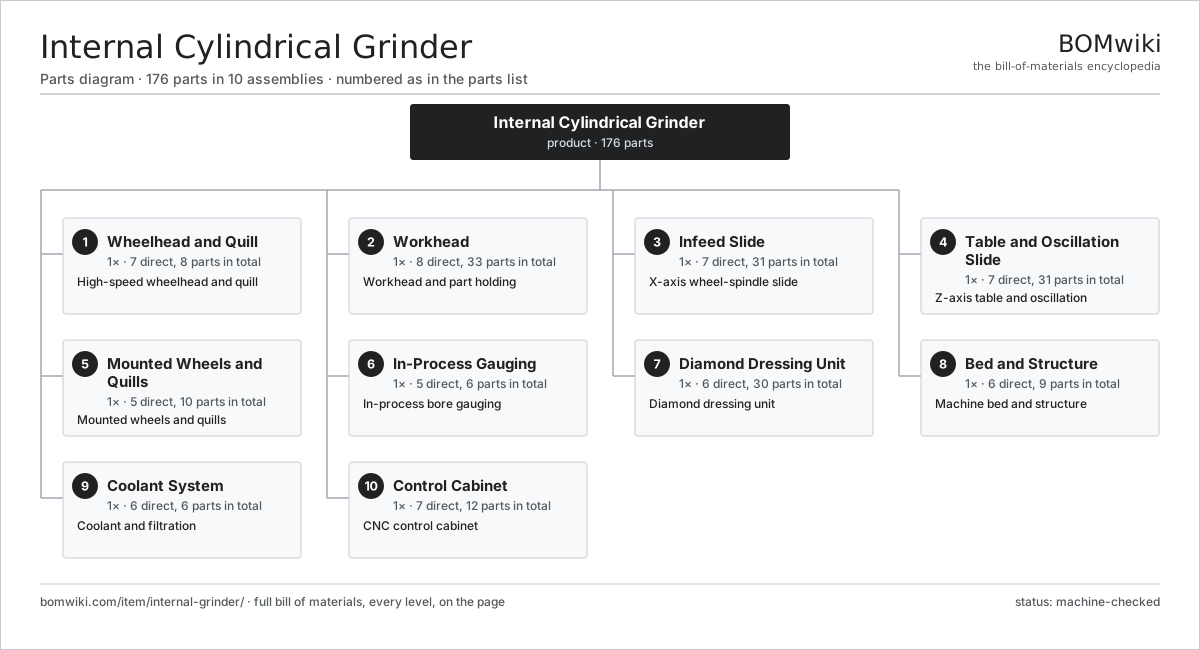
| # | Part | Qty | What it does |
|---|---|---|---|
| 1 | Wheelhead and Quill 7 parts | 1× | High-speed wheelhead and quill |
| 2 | Workhead 8 parts | 1× | Workhead and part holding |
| 3 | Infeed Slide 7 parts | 1× | X-axis wheel-spindle slide |
| 4 | Table and Oscillation Slide 7 parts | 1× | Z-axis table and oscillation |
| 5 | Mounted Wheels and Quills 5 parts | 1× | Mounted wheels and quills |
| 6 | In-Process Gauging 5 parts | 1× | In-process bore gauging |
| 7 | Diamond Dressing Unit 6 parts | 1× | Diamond dressing unit |
| 8 | Bed and Structure 6 parts | 1× | Machine bed and structure |
| 9 | Coolant System 6 parts | 1× | Coolant and filtration |
| 10 | Control Cabinet 7 parts | 1× | CNC control cabinet |
3D model
No 3D model yet. Have a CAD file of this? Add a 3D model — STL renders right on this page; STEP, FreeCAD, and OpenSCAD sources are welcome too (openly licensed, like all 3D models on BOMwiki).
Build & assembly graph
expand / collapse · shared sub-assemblies converge · links to related products · est. labourTap an assembly to expand/collapse · tap a part to open it · use “Open page” for any node · drag to pan, scroll to zoom.
Bill of materials for Internal Cylindrical Grinder
10 top-level lines · 90 rows shown · 176 parts total · indented to 3 levels| # | Item / sub-assembly | Part no. | Qty/assy | Ext. qty | Parts | Type |
|---|---|---|---|---|---|---|
| 1 | Wheelhead and Quill 7 parts | internal-grinder-wheelhead | 1× | 1 | 8 | assembly |
| 1.1 | Spindle Cartridge | internal-grinder-spindle-cartridge | 1× | 1 | · | part |
| 1.2 | Air-Bearing Sleeve | internal-grinder-air-bearing | 1× | 1 | · | part |
| 1.3 | Spindle Motor | internal-grinder-spindle-motor | 1× | 1 | · | part |
| 1.4 | Wheel Quill | internal-grinder-quill | 1× | 1 | · | part |
| 1.5 | Quill Collet | internal-grinder-quill-collet | 1× | 1 | · | part |
| 1.6 | Bearing Air Supply | internal-grinder-spindle-air-supply | 1× | 1 | · | part |
| 1.7 | Ball Bearing | ball-bearing | 2× | 2 | · | part |
| 2 | Workhead 8 parts | internal-grinder-workhead | 1× | 1 | 33 | assembly |
| 2.1 | Workhead Spindle | internal-grinder-workhead-spindle | 1× | 1 | · | part |
| 2.2 | Work Chuck | internal-grinder-chuck | 1× | 1 | · | part |
| 2.3 | Magnetic Face Plate | internal-grinder-magnetic-plate | 1× | 1 | · | part |
| 2.4 | Shoe Support | internal-grinder-shoe-support | 1× | 1 | · | part |
| 2.5 | Workhead Drive | internal-grinder-workhead-drive | 1× | 1 | · | part |
| 2.6 | Ball Bearing | ball-bearing | 3× | 3 | · | part |
| 2.7 | Servo Motor 4 parts | servo-motor | 1× | 1 | 24 | assembly |
| 2.7.1 | Stator Assembly 3 parts + deeper › | stator-assembly | 1× | 1 | 3 | assembly |
| 2.7.2 | Rotor Assembly 4 parts + deeper › | rotor-assembly | 1× | 1 | 19 | assembly |
| 2.7.3 | Encoder | encoder | 1× | 1 | · | part |
| 2.7.4 | Motor Housing | motor-housing | 1× | 1 | · | part |
| 2.8 | Encoder | encoder | 1× | 1 | · | part |
| 3 | Infeed Slide 7 parts | internal-grinder-infeed-slide | 1× | 1 | 31 | assembly |
| 3.1 | Cross Slide | internal-grinder-x-slide | 1× | 1 | · | part |
| 3.2 | X Guideway | internal-grinder-x-guideway | 1× | 1 | · | part |
| 3.3 | Ball Screw | ball-screw | 1× | 1 | · | part |
| 3.4 | Servo Motor 4 parts | servo-motor | 1× | 1 | 24 | assembly |
| 3.4.1 | Stator Assembly 3 parts + deeper › | stator-assembly | 1× | 1 | 3 | assembly |
| 3.4.2 | Rotor Assembly 4 parts + deeper › | rotor-assembly | 1× | 1 | 19 | assembly |
| 3.4.3 | Encoder | encoder | 1× | 1 | · | part |
| 3.4.4 | Motor Housing | motor-housing | 1× | 1 | · | part |
| 3.5 | Encoder | encoder | 1× | 1 | · | part |
| 3.6 | Fine Infeed Unit | internal-grinder-fine-feed | 1× | 1 | · | part |
| 3.7 | Linear Guide Rail | linear-guide | 2× | 2 | · | part |
| 4 | Table and Oscillation Slide 7 parts | internal-grinder-table-slide | 1× | 1 | 31 | assembly |
| 4.1 | Reciprocating Table | internal-grinder-z-table | 1× | 1 | · | part |
| 4.2 | Z Guideway | internal-grinder-z-guideway | 1× | 1 | · | part |
| 4.3 | Ball Screw | ball-screw | 1× | 1 | · | part |
| 4.4 | Servo Motor 4 parts | servo-motor | 1× | 1 | 24 | assembly |
| 4.4.1 | Stator Assembly 3 parts + deeper › | stator-assembly | 1× | 1 | 3 | assembly |
| 4.4.2 | Rotor Assembly 4 parts + deeper › | rotor-assembly | 1× | 1 | 19 | assembly |
| 4.4.3 | Encoder | encoder | 1× | 1 | · | part |
| 4.4.4 | Motor Housing | motor-housing | 1× | 1 | · | part |
| 4.5 | Oscillation Drive | internal-grinder-oscillation-drive | 1× | 1 | · | part |
| 4.6 | Encoder | encoder | 1× | 1 | · | part |
| 4.7 | Linear Guide Rail | linear-guide | 2× | 2 | · | part |
| 5 | Mounted Wheels and Quills 5 parts | internal-grinder-wheel-set | 1× | 1 | 10 | assembly |
| 5.1 | Mounted Grinding Wheel | internal-grinder-mounted-wheel | 4× | 4 | · | part |
| 5.2 | CBN Bore Wheel | internal-grinder-cbn-wheel | 2× | 2 | · | part |
| 5.3 | Wheel Adapter | internal-grinder-wheel-adapter | 2× | 2 | · | part |
| 5.4 | Face Grinding Attachment | internal-grinder-face-wheel | 1× | 1 | · | part |
| 5.5 | Quill Balancing Ring | internal-grinder-balancing-ring | 1× | 1 | · | part |
| 6 | In-Process Gauging 5 parts | internal-grinder-gauging | 1× | 1 | 6 | assembly |
| 6.1 | In-Process Bore Gauge | internal-grinder-bore-gauge | 1× | 1 | · | part |
| 6.2 | Gauge Fingers | internal-grinder-gauge-fingers | 2× | 2 | · | part |
| 6.3 | Gauge Retract | internal-grinder-gauge-retract | 1× | 1 | · | part |
| 6.4 | Post-Process Gauge | internal-grinder-post-gauge | 1× | 1 | · | part |
| 6.5 | Pressure Sensor | pressure-sensor | 1× | 1 | · | part |
| 7 | Diamond Dressing Unit 6 parts | internal-grinder-dresser | 1× | 1 | 30 | assembly |
| 7.1 | Dresser Post | internal-grinder-dress-spindle | 1× | 1 | · | part |
| 7.2 | Dressing Diamond | internal-grinder-diamond-tool | 2× | 2 | · | part |
| 7.3 | Rotary Dresser | internal-grinder-rotary-dresser | 1× | 1 | · | part |
| 7.4 | Dresser Slide | internal-grinder-dress-slide | 1× | 1 | · | part |
| 7.5 | Ball Screw | ball-screw | 1× | 1 | · | part |
| 7.6 | Servo Motor 4 parts | servo-motor | 1× | 1 | 24 | assembly |
| 7.6.1 | Stator Assembly 3 parts + deeper › | stator-assembly | 1× | 1 | 3 | assembly |
| 7.6.2 | Rotor Assembly 4 parts + deeper › | rotor-assembly | 1× | 1 | 19 | assembly |
| 7.6.3 | Encoder | encoder | 1× | 1 | · | part |
| 7.6.4 | Motor Housing | motor-housing | 1× | 1 | · | part |
| 8 | Bed and Structure 6 parts | internal-grinder-bed | 1× | 1 | 9 | assembly |
| 8.1 | Machine Bed | internal-grinder-bed-casting | 1× | 1 | · | part |
| 8.2 | Wheelhead Column | internal-grinder-column | 1× | 1 | · | part |
| 8.3 | Leveling Mount | internal-grinder-leveling | 4× | 4 | · | part |
| 8.4 | Machine Enclosure | internal-grinder-enclosure | 1× | 1 | · | part |
| 8.5 | Loader Interface | internal-grinder-loader-interface | 1× | 1 | · | part |
| 8.6 | Fastener Set | fastener-set | 1× | 1 | · | part |
| 9 | Coolant System 6 parts | internal-grinder-coolant | 1× | 1 | 6 | assembly |
| 9.1 | Coolant Pump | coolant-pump | 1× | 1 | · | part |
| 9.2 | Coolant Tank | internal-grinder-coolant-tank | 1× | 1 | · | part |
| 9.3 | Filter Unit | internal-grinder-filter-unit | 1× | 1 | · | part |
| 9.4 | Coolant Nozzle | internal-grinder-coolant-nozzle | 1× | 1 | · | part |
| 9.5 | Coolant Chiller | internal-grinder-chiller | 1× | 1 | · | part |
| 9.6 | Pressure Sensor | pressure-sensor | 1× | 1 | · | part |
| 10 | Control Cabinet 7 parts | internal-grinder-controls | 1× | 1 | 12 | assembly |
| 10.1 | CNC Control | internal-grinder-cnc | 1× | 1 | · | part |
| 10.2 | Operator HMI | internal-grinder-hmi | 1× | 1 | · | part |
| 10.3 | Power Supply | power-supply | 1× | 1 | · | part |
| 10.4 | IGBT Power Module | igbt-module | 3× | 3 | · | part |
| 10.5 | Relay | relay | 4× | 4 | · | part |
| 10.6 | Wire Bundle | wire-bundle | 1× | 1 | · | part |
| 10.7 | LCD Panel | lcd-panel | 1× | 1 | · | part |
Related products
same domain, ranked by shared parts Bevel Gear Generator
201 parts · shares 6 with this page
Double-Disc Grinder
153 parts · shares 6 with this page
Bevel Gear Generator
201 parts · shares 6 with this page
Double-Disc Grinder
153 parts · shares 6 with this page
 Radial Forging Machine
288 parts · shares 6 with this page
Radial Forging Machine
288 parts · shares 6 with this page
 Rotary-Table Surface Grinder
172 parts · shares 6 with this page
Universal Cylindrical Grinder
153 parts · shares 6 with this page
Rotary-Table Surface Grinder
172 parts · shares 6 with this page
Universal Cylindrical Grinder
153 parts · shares 6 with this page
 CNC Lathe
511 parts · shares 5 with this page
CNC Lathe
511 parts · shares 5 with this page
Sourcing: possible vendors
Prices, MOQ, and lead times are algorithmic estimates, not quotes, and not claims about these companies. Company mappings are curated by keyword; est. price band $10k–$1M. How estimates work| Vendor | HQ | Specialty | MOQ | Lead time |
|---|---|---|---|---|
|
🇩🇪DMG MORI
dmgmori.com ↗
|
Bielefeld, DE | Machine tools | 5 units | 12–20 wks |
|
🇯🇵Mazak
mazak.com ↗
|
Oguchi, JP | Machine tools | 5 units | 12–20 wks |
| haascnc.com ↗ | Oxnard, US | CNC machine tools | 5 units | 12–20 wks |
|
🇯🇵Okuma
okuma.com ↗
|
Niwa, JP | Machine tools | 5 units | 12–20 wks |
|
🇩🇪Trumpf
trumpf.com ↗
|
Ditzingen, DE | Laser & sheet-metal machines | 5 units | 12–20 wks |
1,101-word article