Servo-Electric Press Brake
ProductOverview
A servo-electric press brake bends sheet metal by pressing a punch into a V-die while the workpiece rests across the die opening. Where a hydraulic press brake moves its ram with oil pressure from a pump, the servo-electric machine drives the ram entirely through electric servo motors. Each motor turns a ball screw through a toothed drive belt, and the screws push the ram down on both ends of the frame. The result is a machine with no hydraulic pump, no oil reservoir, and no proportional valves.
The two drive columns sit at the left and right of the frame, one for the Y1 axis and one for the Y2 axis. A synchronization unit commands both axes so the ram stays level as it descends. Because the ram angle is controlled by two independent position loops rather than by hydraulic flow dividers, the machine can deliberately tilt the ram a few hundredths of a millimetre to correct for an uneven workpiece or asymmetric tooling load.
How servo-electric differs from hydraulic
The clearest difference is energy. A hydraulic press brake runs its pump whenever the machine is on, so it burns power even when the ram is parked. A servo-electric machine draws current only while the ram is actually moving, and it recovers part of that energy during the return stroke through the regenerative servo drivers. Across a typical working day this cuts energy use by roughly half compared with an equivalent hydraulic machine, and the saving is largest on jobs with many short bends separated by handling time.
Speed is the second difference. The ball screws and linear guides let the ram approach the work at 200 mm/s or more, far faster than the controlled flow of a hydraulic ram, and the return is just as quick. The motors hold full torque from a standstill, so the transition from rapid approach to the slow bending speed is immediate and does not depend on valve response time.
Accuracy comes from the feedback path. The position feedback system carries two linear encoders mounted on a strain-isolated bridge, one on each side of the ram. They measure the true ram position to one micron, independent of screw wear or thermal growth, so the CNC closes its loop on where the ram actually is rather than on motor turns. Ram repeatability reaches ±0.005 mm, which translates directly into consistent bend angles from the first part to the last.
A servo-electric machine is also quiet. With no pump and no relief valve, the only sound during a cycle is the belt and screw motion, so noise drops well below the level of a hydraulic unit of the same tonnage. There is no oil to heat, leak, filter, or replace, which removes a recurring maintenance cost and a contamination risk on clean shop floors.
Frame and ram
The frame is a welded steel C-frame built from two thick side frame plates, a fixed lower bed beam, and a moving upper ram beam. A rear tie beam resists frame spread under load. The ram rides on vertical linear guides and adjustable gibs so it tracks straight down without play. The frame is sized so its deflection under full tonnage stays within the range the crowning system can correct.
Tooling and crowning
The tooling holds a segmented punch in an upper holder and a V-die in the lower die holder, secured by quick clamps. The die opening sets the inside radius and the force needed for a given thickness.
Under load the bed and ram bow slightly in the middle, which would otherwise open the bend angle at the centre of a long part. The crowning system cancels this by driving a train of tapered wedges in the bed with a small servo and ball screw, lifting the die rail more in the centre than at the ends. The CNC computes the wedge setting from the programmed tonnage so the bend angle is uniform along the full bending length.
Back gauge and CNC control
The back gauge positions the sheet for each bend. Its X axis sets bend depth and its R axis sets finger height, both on servo ball screws running on linear guides, with fingers the operator slides along the beam. The CNC control runs the whole machine from a touchscreen using a 2D or 3D part drawing, calculating bend sequence, tonnage, and crowning. The control board commands the servo drivers for the Y1, Y2, and gauge axes through a logic power supply and an I/O module.
Safety and electrical
Operator protection centres on the laser finger guard, a beam projected just ahead of the punch tip that stops the ram if it is broken, monitored by a safety relay rated to ISO 13849 PL d. Emergency stops and a two-stage foot pedal complete the operator interface. The electrical cabinet holds the mains disconnect, a line reactor for the servo bus, the auxiliary supply, and the machine wiring harness.
Servo-Electric Press Brake parts and their functions
9 top-level parts · 1,191 parts in total · full bill of materials below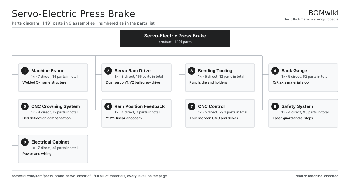
| # | Part | Qty | What it does |
|---|---|---|---|
| 1 | Machine Frame 7 parts | 1× | Welded C-frame structure |
| 2 | Servo Ram Drive 3 parts | 1× | Dual servo Y1/Y2 ballscrew drive |
| 3 | Bending Tooling 5 parts | 1× | Punch, die and holders |
| 4 | Back Gauge 5 parts | 1× | X/R axis material stop |
| 5 | CNC Crowning System 4 parts | 1× | Bed deflection compensation |
| 6 | Ram Position Feedback 4 parts | 1× | Y1/Y2 linear encoders |
| 7 | CNC Control 5 parts | 1× | Touchscreen CNC and drives |
| 8 | Safety System 4 parts | 1× | Laser guard and e-stops |
| 9 | Electrical Cabinet 7 parts | 1× | Power and wiring |
3D model
No 3D model yet. Have a CAD file of this? Add a 3D model — STL renders right on this page; STEP, FreeCAD, and OpenSCAD sources are welcome too (openly licensed, like all 3D models on BOMwiki).
Build & assembly graph
expand / collapse · shared sub-assemblies converge · links to related products · est. labourTap an assembly to expand/collapse · tap a part to open it · use “Open page” for any node · drag to pan, scroll to zoom.
Bill of materials for Servo-Electric Press Brake
9 top-level lines · 105 rows shown · 1,191 parts total · indented to 3 levels| # | Item / sub-assembly | Part no. | Qty/assy | Ext. qty | Parts | Type |
|---|---|---|---|---|---|---|
| 1 | Machine Frame 7 parts | press-brake-servo-electric-frame | 1× | 1 | 14 | assembly |
| 1.1 | Side Frame Plate | press-brake-servo-electric-side-frame | 2× | 2 | · | part |
| 1.2 | Lower Bed Beam | press-brake-servo-electric-bed | 1× | 1 | · | part |
| 1.3 | Upper Ram Beam 3 parts | press-brake-servo-electric-ram | 1× | 1 | 4 | assembly |
| 1.3.1 | Ram Weldment | press-brake-servo-electric-ram-body | 1× | 1 | · | part |
| 1.3.2 | Ram Apron | press-brake-servo-electric-ram-apron | 1× | 1 | · | part |
| 1.3.3 | Linear Guide Rail | linear-guide | 2× | 2 | · | part |
| 1.4 | Rear Tie Beam | press-brake-servo-electric-tie-beam | 1× | 1 | · | part |
| 1.5 | Base Plate | press-brake-servo-electric-base-plate | 1× | 1 | · | part |
| 1.6 | Ram Gib | press-brake-servo-electric-ram-guide | 4× | 4 | · | part |
| 1.7 | Fastener Set | fastener-set | 1× | 1 | · | part |
| 2 | Servo Ram Drive 3 parts | press-brake-servo-electric-ram-drive | 1× | 1 | 155 | assembly |
| 2.1 | Servo Drive Column 9 parts | press-brake-servo-electric-drive-column | 2× | 2 | 34 | assembly |
| 2.1.1 | Servo Motor 4 parts + deeper › | servo-motor | 1× | 2 | 24 | assembly |
| 2.1.2 | Drive Belt | drive-belt | 1× | 2 | · | part |
| 2.1.3 | Drive Pulley | press-brake-servo-electric-drive-pulley | 2× | 4 | · | part |
| 2.1.4 | Ball Screw | ball-screw | 1× | 2 | · | part |
| 2.1.5 | Ballscrew Nut | press-brake-servo-electric-screw-nut | 1× | 2 | · | part |
| 2.1.6 | Linear Guide Rail | linear-guide | 1× | 2 | · | part |
| 2.1.7 | Ball Bearing | ball-bearing | 2× | 4 | · | part |
| 2.1.8 | Belt Tensioner | press-brake-servo-electric-belt-tensioner | 1× | 2 | · | part |
| 2.1.9 | Oil Seal | oil-seal | 1× | 2 | · | part |
| 2.2 | Y-Axis Sync Unit 4 parts | press-brake-servo-electric-sync-controller | 1× | 1 | 86 | assembly |
| 2.2.1 | Bare PCB | pcb-bare | 1× | 1 | · | part |
| 2.2.2 | Microcontroller | mcu | 1× | 1 | · | part |
| 2.2.3 | SMD Passive (R/C/L) | smd-passives | 80× | 80 | · | part |
| 2.2.4 | Connector | connector | 4× | 4 | · | part |
| 2.3 | Fastener Set | fastener-set | 1× | 1 | · | part |
| 3 | Bending Tooling 5 parts | press-brake-servo-electric-tooling | 1× | 1 | 12 | assembly |
| 3.1 | Bending Punch | press-brake-servo-electric-punch | 1× | 1 | · | part |
| 3.2 | V-Die | press-brake-servo-electric-v-die | 1× | 1 | · | part |
| 3.3 | Punch Holder | press-brake-servo-electric-punch-holder | 1× | 1 | · | part |
| 3.4 | Die Holder | press-brake-servo-electric-die-holder | 1× | 1 | · | part |
| 3.5 | Tool Clamp | press-brake-servo-electric-tool-clamp | 8× | 8 | · | part |
| 4 | Back Gauge 5 parts | press-brake-servo-electric-back-gauge | 1× | 1 | 62 | assembly |
| 4.1 | Back Gauge Beam | press-brake-servo-electric-gauge-beam | 1× | 1 | · | part |
| 4.2 | Gauge Finger | press-brake-servo-electric-gauge-finger | 4× | 4 | · | part |
| 4.3 | X-Axis Drive 4 parts | press-brake-servo-electric-x-axis-drive | 1× | 1 | 28 | assembly |
| 4.3.1 | Servo Motor 4 parts + deeper › | servo-motor | 1× | 1 | 24 | assembly |
| 4.3.2 | Ball Screw | ball-screw | 1× | 1 | · | part |
| 4.3.3 | Ball Bearing | ball-bearing | 2× | 2 | · | part |
| 4.3.4 | Drive Belt | drive-belt | 1× | 1 | · | part |
| 4.4 | R-Axis Drive 3 parts | press-brake-servo-electric-r-axis-drive | 1× | 1 | 27 | assembly |
| 4.4.1 | Servo Motor 4 parts + deeper › | servo-motor | 1× | 1 | 24 | assembly |
| 4.4.2 | Ball Screw | ball-screw | 1× | 1 | · | part |
| 4.4.3 | Ball Bearing | ball-bearing | 2× | 2 | · | part |
| 4.5 | Linear Guide Rail | linear-guide | 2× | 2 | · | part |
| 5 | CNC Crowning System 4 parts | press-brake-servo-electric-crowning-system | 1× | 1 | 12 | assembly |
| 5.1 | Crowning Wedge | press-brake-servo-electric-crowning-wedge | 6× | 6 | · | part |
| 5.2 | Crowning Servo | press-brake-servo-electric-crowning-motor | 1× | 1 | · | part |
| 5.3 | Ball Screw | ball-screw | 1× | 1 | · | part |
| 5.4 | Coil Spring | coil-spring | 4× | 4 | · | part |
| 6 | Ram Position Feedback 4 parts | press-brake-servo-electric-position-feedback | 1× | 1 | 7 | assembly |
| 6.1 | Linear Encoder Scale | press-brake-servo-electric-linear-encoder | 2× | 2 | · | part |
| 6.2 | Encoder Bridge Bracket | press-brake-servo-electric-encoder-bracket | 2× | 2 | · | part |
| 6.3 | Connector | connector | 2× | 2 | · | part |
| 6.4 | Wire Bundle | wire-bundle | 1× | 1 | · | part |
| 7 | CNC Control 5 parts | press-brake-servo-electric-cnc-control | 1× | 1 | 793 | assembly |
| 7.1 | CNC Controller Board 4 parts | press-brake-servo-electric-cnc-board | 1× | 1 | 235 | assembly |
| 7.1.1 | Bare PCB | pcb-bare | 1× | 1 | · | part |
| 7.1.2 | Microcontroller | mcu | 2× | 2 | · | part |
| 7.1.3 | SMD Passive (R/C/L) | smd-passives | 220× | 220 | · | part |
| 7.1.4 | Connector | connector | 12× | 12 | · | part |
| 7.2 | Touchscreen HMI 4 parts | press-brake-servo-electric-touchscreen | 1× | 1 | 63 | assembly |
| 7.2.1 | LCD Panel | lcd-panel | 1× | 1 | · | part |
| 7.2.2 | Touch Digitizer Glass | press-brake-servo-electric-touch-glass | 1× | 1 | · | part |
| 7.2.3 | Bare PCB | pcb-bare | 1× | 1 | · | part |
| 7.2.4 | SMD Passive (R/C/L) | smd-passives | 60× | 60 | · | part |
| 7.3 | Servo Driver 4 parts | press-brake-servo-electric-servo-driver | 3× | 3 | 143 | assembly |
| 7.3.1 | Bare PCB | pcb-bare | 1× | 3 | · | part |
| 7.3.2 | Microcontroller | mcu | 1× | 3 | · | part |
| 7.3.3 | SMD Passive (R/C/L) | smd-passives | 140× | 420 | · | part |
| 7.3.4 | IGBT Output Stage | press-brake-servo-electric-igbt-stage | 1× | 3 | · | part |
| 7.4 | Power Supply | power-supply | 1× | 1 | · | part |
| 7.5 | I/O Module 4 parts | press-brake-servo-electric-io-module | 1× | 1 | 65 | assembly |
| 7.5.1 | Bare PCB | pcb-bare | 1× | 1 | · | part |
| 7.5.2 | Relay | relay | 8× | 8 | · | part |
| 7.5.3 | Connector | connector | 16× | 16 | · | part |
| 7.5.4 | SMD Passive (R/C/L) | smd-passives | 40× | 40 | · | part |
| 8 | Safety System 4 parts | press-brake-servo-electric-safety-system | 1× | 1 | 95 | assembly |
| 8.1 | Laser Finger Guard 4 parts | press-brake-servo-electric-laser-guard | 1× | 1 | 53 | assembly |
| 8.1.1 | Laser Emitter | press-brake-servo-electric-laser-emitter | 1× | 1 | · | part |
| 8.1.2 | Laser Receiver | press-brake-servo-electric-laser-receiver | 1× | 1 | · | part |
| 8.1.3 | Bare PCB | pcb-bare | 1× | 1 | · | part |
| 8.1.4 | SMD Passive (R/C/L) | smd-passives | 50× | 50 | · | part |
| 8.2 | Safety Relay 3 parts | press-brake-servo-electric-safety-relay | 1× | 1 | 35 | assembly |
| 8.2.1 | Bare PCB | pcb-bare | 1× | 1 | · | part |
| 8.2.2 | Relay | relay | 4× | 4 | · | part |
| 8.2.3 | SMD Passive (R/C/L) | smd-passives | 30× | 30 | · | part |
| 8.3 | Emergency Stop Button | press-brake-servo-electric-estop | 2× | 2 | · | part |
| 8.4 | Foot Pedal 3 parts | press-brake-servo-electric-foot-pedal | 1× | 1 | 5 | assembly |
| 8.4.1 | Pedal Switch | press-brake-servo-electric-pedal-switch | 2× | 2 | · | part |
| 8.4.2 | Coil Spring | coil-spring | 2× | 2 | · | part |
| 8.4.3 | Wire Bundle | wire-bundle | 1× | 1 | · | part |
| 9 | Electrical Cabinet 7 parts | press-brake-servo-electric-electrical-cabinet | 1× | 1 | 41 | assembly |
| 9.1 | Cabinet Enclosure 3 parts | press-brake-servo-electric-cabinet-enclosure | 1× | 1 | 7 | assembly |
| 9.1.1 | Sheet Metal Panel | sheet-panel | 5× | 5 | · | part |
| 9.1.2 | Cabinet Fan | press-brake-servo-electric-cabinet-fan | 1× | 1 | · | part |
| 9.1.3 | Fastener Set | fastener-set | 1× | 1 | · | part |
| 9.2 | Main Breaker | press-brake-servo-electric-main-breaker | 1× | 1 | · | part |
| 9.3 | Line Reactor | press-brake-servo-electric-line-reactor | 1× | 1 | · | part |
| 9.4 | Power Supply | power-supply | 1× | 1 | · | part |
| 9.5 | Wire Bundle | wire-bundle | 1× | 1 | · | part |
| 9.6 | Connector | connector | 24× | 24 | · | part |
| 9.7 | Relay | relay | 6× | 6 | · | part |
Related products
same domain, ranked by shared parts Crankshaft Grinder
511 parts · shares 7 with this page
Crankshaft Grinder
511 parts · shares 7 with this page
 Creep-Feed Grinder
571 parts · shares 7 with this page
Creep-Feed Grinder
571 parts · shares 7 with this page
 Railway Wheel Lathe
1,201 parts · shares 7 with this page
Railway Wheel Lathe
1,201 parts · shares 7 with this page
 Rotary-Table Surface Grinder
172 parts · shares 7 with this page
Rotary-Table Surface Grinder
172 parts · shares 7 with this page
 Forging Trim Press
190 parts · shares 6 with this page
Forging Trim Press
190 parts · shares 6 with this page
Sourcing: possible vendors
Prices, MOQ, and lead times are algorithmic estimates, not quotes, and not claims about these companies. Company mappings are curated by keyword; est. price band $10k–$1M. How estimates work| Vendor | HQ | Specialty | MOQ | Lead time |
|---|---|---|---|---|
|
🇩🇪DMG MORI
dmgmori.com ↗
|
Bielefeld, DE | Machine tools | 5 units | 12–20 wks |
|
🇯🇵Mazak
mazak.com ↗
|
Oguchi, JP | Machine tools | 5 units | 12–20 wks |
| haascnc.com ↗ | Oxnard, US | CNC machine tools | 5 units | 12–20 wks |
|
🇯🇵Okuma
okuma.com ↗
|
Niwa, JP | Machine tools | 5 units | 12–20 wks |
|
🇩🇪Trumpf
trumpf.com ↗
|
Ditzingen, DE | Laser & sheet-metal machines | 5 units | 12–20 wks |
1,062-word article