Electrochemical Machining Machine
ProductOverview
An electrochemical machining machine removes metal from a workpiece by controlled anodic dissolution rather than by cutting or grinding. The workpiece is connected as the anode and a shaped tool as the cathode. A low voltage of 8 to 25 V drives a heavy direct current, from several hundred to several thousand amps, through a flowing salt electrolyte that fills a narrow gap of about 0.2 to 0.5 mm between tool and work. Metal leaves the workpiece surface ion by ion and is carried away as hydroxide sludge in the electrolyte. Because the tool never touches the work, it does not wear, and the process cuts hard alloys, hardened steels, and nickel superalloys as easily as soft metals. The machine is built around a DC Power Supply, a Tool Feed Ram, an Electrolyte Supply System, a Machining Chamber, and a Control Cabinet, with a Sludge Separation System and a Fume Extraction System handling the byproducts.
How Anodic Dissolution Works
When current passes between the electrodes, iron and other metal atoms at the anode surface give up electrons and enter the electrolyte as metal ions, which combine with hydroxide to form an insoluble metal-hydroxide floc. At the cathode, water is reduced and hydrogen gas is released. The rate of metal removal follows Faraday's law, so it depends almost entirely on the current passed and not on the hardness of the material. The shape of the cut comes from the gap: dissolution is fastest where the gap is smallest and the current density is highest, so the cathode geometry is reproduced as a near mirror image in the workpiece. The Cathode Tool is therefore machined to the inverse of the cavity wanted, and it can be reused indefinitely because it carries no mechanical load and suffers no wear.
High-Current Power Supply
The DC Power Supply provides the regulated low-voltage DC the process needs. A Power Transformer steps the line down to a low secondary voltage, a Rectifier Stack of thyristors converts it to phase-controlled DC, and laminated DC Output Busbar conductors carry the current to the cathode and the worktable with little voltage drop. A Current Shunt measures the current so the control can hold the target current density in A/cm2 as the cut develops. Many machines add a Pulse Module for pulsed ECM, switching the current into short pulses so fresh electrolyte and sludge clear the gap between pulses, which sharpens edge definition and improves finish. The whole stack is water cooled through the Supply Cooling Unit unit, and a Output Contactor isolates the output the instant a fault is detected.
Electrolyte and Sludge Handling
Electrolyte does three jobs: it carries the current, it removes dissolved metal, and it carries away the heat and hydrogen from the gap. The Electrolyte Supply System pumps sodium nitrate or sodium chloride solution from the Electrolyte Tank through the gap at 10 to 60 L/min and 0.5 to 2 MPa using a Electrolyte Supply Pump. A Electrolyte Heat Exchanger holds the temperature within about a kelvin, because conductivity changes roughly 2 percent per kelvin and that would shift the removal rate. A Conductivity Probe and a pH Probe track the chemistry, a Dosing Pump corrects pH as hydroxides form, and a Flow Meter guards against flow loss that would let the electrolyte boil and pit the surface. A Cartridge Filter removes fine particles before they bridge the gap. The dissolved metal leaves as floc, so the Sludge Separation System runs the returning electrolyte through a Settling Tank and a Sludge Centrifuge, with a Filter Press pressing the hydroxide into a dry cake for disposal while a Clarified Return Pump returns clean electrolyte to the tank.
Tool, Gap, and Feed Control
Holding the gap constant is the central control problem. As metal dissolves, the Tool Feed Ram advances the Cathode Tool Holder into the workpiece at 0.1 to 10 mm/min so the gap stays near its setpoint. The ram rides on a Ball Screw and Linear Guide Rail driven by a Servo Motor, with an Ram Linear Scale closing the position loop and an Ram Counterbalance offsetting the toolhead weight. The cathode mounts through an Tool Insulator that keeps it electrically separate from the frame, fed by a flexible Cathode Busbar and supplied through an Tool Flow Passage for forward flushing. The Gap Control Electronics electronics infer the gap from the Cell Voltage Probe reading on the Gap Monitor Board: if the gap closes too far the cell voltage drops, and an Short-Circuit Detector circuit trips the Output Contactor and retracts the ram within milliseconds to prevent an arc that would damage both tool and work.
Control and Safety
The Control Cabinet ties the machine together. An Process CNC runs the feed and current profile, ramping voltage and feed to keep current density on target as the cavity forms, while an Process PLC sequences the pumps, valves, dosing, and sludge handling and refuses to apply power until electrolyte flow and chemistry are within limits. The Servo Drive closes the feed loop and the operator works from the Operator Panel. Because the cathode reaction releases hydrogen, the Fume Extraction System draws the chamber air through a Mist Eliminator and a Exhaust Scrubber, and Hydrogen Sensor detectors cut power if hydrogen rises toward its flammable range. The Machining Chamber itself is sealed against the corrosive spray and interlocked so power drops before the Chamber Door can open.
Applications and Variants
ECM is used where parts are hard to machine, hard to reach, or must be free of tool marks and residual stress. Common work includes turbine and compressor blades in nickel and titanium alloys, forging and extrusion dies, gun barrels, and surgical and aerospace parts in tough materials. Because there is no cutting force and no heat-affected layer, thin and delicate features survive that would distort under a conventional tool. Variants include die-sinking ECM, in which the Tool Feed Ram sinks a shaped cathode straight down; electrochemical drilling and shaped-tube drilling for small deep holes; and pulsed ECM, which uses the Pulse Module for tighter tolerances and finer finish. Larger machines reach into the multi-thousand-amp range for big dies, while smaller pulsed units work to micron-scale features.
Electrochemical Machining Machine parts and their functions
10 top-level parts · 107 parts in total · full bill of materials below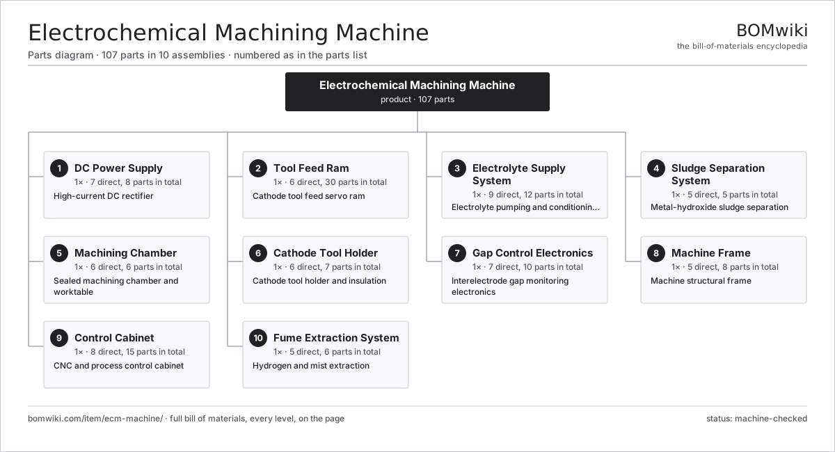
| # | Part | Qty | What it does |
|---|---|---|---|
| 1 | DC Power Supply 7 parts | 1× | High-current DC rectifier |
| 2 | Tool Feed Ram 6 parts | 1× | Cathode tool feed servo ram |
| 3 | Electrolyte Supply System 9 parts | 1× | Electrolyte pumping and conditioning plant |
| 4 | Sludge Separation System 5 parts | 1× | Metal-hydroxide sludge separation |
| 5 | Machining Chamber 6 parts | 1× | Sealed machining chamber and worktable |
| 6 | Cathode Tool Holder 6 parts | 1× | Cathode tool holder and insulation |
| 7 | Gap Control Electronics 7 parts | 1× | Interelectrode gap monitoring electronics |
| 8 | Machine Frame 5 parts | 1× | Machine structural frame |
| 9 | Control Cabinet 8 parts | 1× | CNC and process control cabinet |
| 10 | Fume Extraction System 5 parts | 1× | Hydrogen and mist extraction |
3D model
No 3D model yet. Have a CAD file of this? Add a 3D model — STL renders right on this page; STEP, FreeCAD, and OpenSCAD sources are welcome too (openly licensed, like all 3D models on BOMwiki).
Build & assembly graph
expand / collapse · shared sub-assemblies converge · links to related products · est. labourTap an assembly to expand/collapse · tap a part to open it · use “Open page” for any node · drag to pan, scroll to zoom.
Bill of materials for Electrochemical Machining Machine
10 top-level lines · 78 rows shown · 107 parts total · indented to 3 levels| # | Item / sub-assembly | Part no. | Qty/assy | Ext. qty | Parts | Type |
|---|---|---|---|---|---|---|
| 1 | DC Power Supply 7 parts | ecm-power-supply | 1× | 1 | 8 | assembly |
| 1.1 | Power Transformer | ecm-transformer | 1× | 1 | · | part |
| 1.2 | Rectifier Stack | ecm-rectifier-stack | 1× | 1 | · | part |
| 1.3 | DC Output Busbar | ecm-dc-busbar | 2× | 2 | · | part |
| 1.4 | Pulse Module | ecm-pulse-module | 1× | 1 | · | part |
| 1.5 | Current Shunt | ecm-shunt-sensor | 1× | 1 | · | part |
| 1.6 | Supply Cooling Unit | ecm-supply-cooling | 1× | 1 | · | part |
| 1.7 | Output Contactor | ecm-power-contactor | 1× | 1 | · | part |
| 2 | Tool Feed Ram 6 parts | ecm-feed-ram | 1× | 1 | 30 | assembly |
| 2.1 | Ram Slide | ecm-ram-slide | 1× | 1 | · | part |
| 2.2 | Ball Screw | ball-screw | 1× | 1 | · | part |
| 2.3 | Linear Guide Rail | linear-guide | 2× | 2 | · | part |
| 2.4 | Servo Motor 4 parts | servo-motor | 1× | 1 | 24 | assembly |
| 2.4.1 | Stator Assembly 3 parts + deeper › | stator-assembly | 1× | 1 | 3 | assembly |
| 2.4.2 | Rotor Assembly 4 parts + deeper › | rotor-assembly | 1× | 1 | 19 | assembly |
| 2.4.3 | Encoder | encoder | 1× | 1 | · | part |
| 2.4.4 | Motor Housing | motor-housing | 1× | 1 | · | part |
| 2.5 | Ram Linear Scale | ecm-ram-scale | 1× | 1 | · | part |
| 2.6 | Ram Counterbalance | ecm-ram-counterbalance | 1× | 1 | · | part |
| 3 | Electrolyte Supply System 9 parts | ecm-electrolyte-system | 1× | 1 | 12 | assembly |
| 3.1 | Electrolyte Tank | ecm-electrolyte-tank | 1× | 1 | · | part |
| 3.2 | Electrolyte Supply Pump | ecm-supply-pump | 2× | 2 | · | part |
| 3.3 | Electrolyte Heat Exchanger | ecm-heat-exchanger | 1× | 1 | · | part |
| 3.4 | Cartridge Filter | ecm-cartridge-filter | 2× | 2 | · | part |
| 3.5 | Conductivity Probe | ecm-conductivity-sensor | 1× | 1 | · | part |
| 3.6 | pH Probe | ecm-ph-sensor | 1× | 1 | · | part |
| 3.7 | Flow Meter | ecm-flow-meter | 2× | 2 | · | part |
| 3.8 | Dosing Pump | ecm-dosing-pump | 1× | 1 | · | part |
| 3.9 | Supply Valve Block | ecm-supply-valve-block | 1× | 1 | · | part |
| 4 | Sludge Separation System 5 parts | ecm-sludge-system | 1× | 1 | 5 | assembly |
| 4.1 | Settling Tank | ecm-settling-tank | 1× | 1 | · | part |
| 4.2 | Sludge Centrifuge | ecm-centrifuge | 1× | 1 | · | part |
| 4.3 | Sludge Pump | ecm-sludge-pump | 1× | 1 | · | part |
| 4.4 | Filter Press | ecm-filter-press | 1× | 1 | · | part |
| 4.5 | Clarified Return Pump | ecm-clarified-pump | 1× | 1 | · | part |
| 5 | Machining Chamber 6 parts | ecm-machining-chamber | 1× | 1 | 6 | assembly |
| 5.1 | Chamber Enclosure | ecm-chamber-enclosure | 1× | 1 | · | part |
| 5.2 | Worktable | ecm-worktable | 1× | 1 | · | part |
| 5.3 | Workpiece Clamp | ecm-workpiece-clamp | 1× | 1 | · | part |
| 5.4 | Chamber Door | ecm-chamber-door | 1× | 1 | · | part |
| 5.5 | Drain Manifold | ecm-drain-manifold | 1× | 1 | · | part |
| 5.6 | O-Ring Set | oring-set | 1× | 1 | · | part |
| 6 | Cathode Tool Holder 6 parts | ecm-tool-holder | 1× | 1 | 7 | assembly |
| 6.1 | Cathode Tool | ecm-cathode-tool | 1× | 1 | · | part |
| 6.2 | Tool Insulator | ecm-tool-insulator | 1× | 1 | · | part |
| 6.3 | Cathode Busbar | ecm-tool-busbar | 1× | 1 | · | part |
| 6.4 | Tool Flow Passage | ecm-tool-flow-passage | 1× | 1 | · | part |
| 6.5 | Tool Mounting Seal | ecm-tool-seal | 1× | 1 | · | part |
| 6.6 | Oil Seal | oil-seal | 2× | 2 | · | part |
| 7 | Gap Control Electronics 7 parts | ecm-gap-control | 1× | 1 | 10 | assembly |
| 7.1 | Gap Monitor Board | ecm-gap-monitor-board | 1× | 1 | · | part |
| 7.2 | Short-Circuit Detector | ecm-short-detect | 1× | 1 | · | part |
| 7.3 | Cell Voltage Probe | ecm-cell-voltage-probe | 1× | 1 | · | part |
| 7.4 | Bare PCB | pcb-bare | 1× | 1 | · | part |
| 7.5 | Microcontroller | mcu | 1× | 1 | · | part |
| 7.6 | SMD Passive (R/C/L) | smd-passives | 1× | 1 | · | part |
| 7.7 | Connector | connector | 4× | 4 | · | part |
| 8 | Machine Frame 5 parts | ecm-frame | 1× | 1 | 8 | assembly |
| 8.1 | Base Casting | ecm-base-casting | 1× | 1 | · | part |
| 8.2 | Ram Column | ecm-column | 1× | 1 | · | part |
| 8.3 | Frame Coating | ecm-frame-coating | 1× | 1 | · | part |
| 8.4 | Leveling Foot | ecm-leveling-foot | 4× | 4 | · | part |
| 8.5 | Fastener Set | fastener-set | 1× | 1 | · | part |
| 9 | Control Cabinet 8 parts | ecm-control-cabinet | 1× | 1 | 15 | assembly |
| 9.1 | Process CNC | ecm-cnc-unit | 1× | 1 | · | part |
| 9.2 | Process PLC | ecm-process-plc | 1× | 1 | · | part |
| 9.3 | Servo Drive | ecm-servo-drive | 1× | 1 | · | part |
| 9.4 | Power Supply | power-supply | 1× | 1 | · | part |
| 9.5 | Operator Panel | ecm-operator-panel | 1× | 1 | · | part |
| 9.6 | Relay | relay | 8× | 8 | · | part |
| 9.7 | Wire Bundle | wire-bundle | 1× | 1 | · | part |
| 9.8 | LCD Panel | lcd-panel | 1× | 1 | · | part |
| 10 | Fume Extraction System 5 parts | ecm-fume-system | 1× | 1 | 6 | assembly |
| 10.1 | Extraction Fan | ecm-extract-fan | 1× | 1 | · | part |
| 10.2 | Mist Eliminator | ecm-mist-eliminator | 1× | 1 | · | part |
| 10.3 | Exhaust Scrubber | ecm-scrubber | 1× | 1 | · | part |
| 10.4 | Hydrogen Sensor | ecm-h2-sensor | 2× | 2 | · | part |
| 10.5 | Extraction Duct | ecm-extract-duct | 1× | 1 | · | part |
Related products
same domain, ranked by shared parts Bevel Gear Generator
201 parts · shares 5 with this page
Camshaft Grinder
489 parts · shares 5 with this page
Centering and Facing Machine
1,419 parts · shares 5 with this page
Bevel Gear Generator
201 parts · shares 5 with this page
Camshaft Grinder
489 parts · shares 5 with this page
Centering and Facing Machine
1,419 parts · shares 5 with this page
 CO2 Laser Cutting Machine
227 parts · shares 5 with this page
CO2 Laser Cutting Machine
227 parts · shares 5 with this page
 Crankshaft Grinder
511 parts · shares 5 with this page
Crankshaft Grinder
511 parts · shares 5 with this page
Sourcing: possible vendors
Prices, MOQ, and lead times are algorithmic estimates, not quotes, and not claims about these companies. Company mappings are curated by keyword; est. price band $10k–$1M. How estimates work| Vendor | HQ | Specialty | MOQ | Lead time |
|---|---|---|---|---|
|
🇩🇪DMG MORI
dmgmori.com ↗
|
Bielefeld, DE | Machine tools | 5 units | 12–20 wks |
|
🇯🇵Mazak
mazak.com ↗
|
Oguchi, JP | Machine tools | 5 units | 12–20 wks |
| haascnc.com ↗ | Oxnard, US | CNC machine tools | 5 units | 12–20 wks |
|
🇯🇵Okuma
okuma.com ↗
|
Niwa, JP | Machine tools | 5 units | 12–20 wks |
|
🇩🇪Trumpf
trumpf.com ↗
|
Ditzingen, DE | Laser & sheet-metal machines | 5 units | 12–20 wks |
1,080-word article