CNC Plasma Cutting Table
ProductAlso known as: CNC Plasma Cutting Machine
Overview
A CNC plasma cutting table is a high-productivity oxy-fuel replacement for cutting ferrous and non-ferrous metals. The plasma arc, a constricted column of ionized gas at 15,000+ Kelvin, melts and ejects the material in microseconds, leaving a clean kerf with minimal heat-affected zone. No lead-in/lead-out arcs, no slag, and the ability to nest hundreds of parts per sheet make plasma the standard for job shops and fabricators.
The system comprises a large gantry frame spanning the work area, with two servo-driven X and Y axes. A stepper-controlled Z height servo maintains accurate arc length. The CNC controller interprets DXF part drawings, nests them on material, and executes cutting sequences. A water or downdraft table collects fumes and cutting debris.
Modern systems achieve 50–100 meter of cutting per minute at routine tolerances, with minimal manual work. No operator skill required for torch angle or standoff, the machine handles it all.
How it works
Part Nesting: The operator loads a DXF drawing or raster image of sheet material into the CNC controller. The software (Mach3, TurboCNC, or a proprietary PLC) nests parts to minimize scrap and plan the cutting sequence (outer profile first, then internal features). The machine calculates optimal feed rates based on material thickness and gas type.
Torch Approach: The X servo and Y servo rapids the torch to the first cut start position above the sheet. The Z stepper lowers the torch to a standoff height (typically 3–6 mm above the sheet).
Pilot Arc: The plasma power supply initiates a pilot arc between the tungsten electrode and the nozzle. This low-current arc (8–15 A) ionizes the gas, creating the plasma column. The pilot arc runs regardless of whether the torch is over the workpiece; it consumes little power and keeps the electrode ready to cut.
Piercing: When the torch reaches the cutting zone, the power jumps to full output amperage (80–300 A, depending on part thickness). The plasma jet (now 1–2 mm wide) pierces the material, blowing a hole through within 0.5–2 seconds. During piercing, the Z axis may lower an additional 1–2 mm to establish full penetration and heat the edge.
Cutting: Once the hole is established, the X/Y servos move the torch along the profile at programmed feed rate (typically 3–8 m/min for 6 mm mild steel). The arc voltage sensor continuously monitors the gap; the Z stepper adjusts height to hold voltage (and thus gap) constant. This feedback prevents the torch from plunging into thick material or rising too high on thin sections.
Gas and Cooling: Compressed air or nitrogen flows through the swirl cup, creating a vortex that stabilizes and cools the arc. The high-velocity jet ejects molten material (sometimes reaching 6000 K) and keeps the nozzle cool through forced convection. Without gas, the torch overheats in under 10 seconds.
Fume Capture: Hot gas, metal vapor, and sound emerge below the torch. A water table (bath) or downdraft plenum collects the fumes. Water tables submerge the workpiece, quenching the hot debris and capturing 70–90% of fumes; downdraft tables rely on negative pressure to pull fumes laterally. Both feed into dust collectors.
Piercing and Lead-In Strategy
Piercing is the most damaging phase for consumables. The nozzle experiences a 5–10× current concentration and extreme thermal shock. Piercing time (typically 0.5–2 seconds) consumes as much nozzle life as 10–20 seconds of normal cutting.
To extend consumable life, modern CNC systems employ:
- Low-amperage pilot: The pilot arc runs at 10–15 A until the torch is positioned over the start point. Current jumps only during piercing and cutting, reducing idle electrode erosion.
- Lead-in arcs: A short (5–10 mm) lead-in line outside the final part profile allows the arc to stabilize before cutting the actual geometry. The lead-in is discarded.
- Ramp-up delay: Current increases gradually over 0.1–0.3 seconds during pierce, reducing thermal shock.
Height Control and Arc Voltage Feedback
The optimal standoff distance is 4–8 mm (material dependent). Too close and the nozzle risks hitting spatter; too far and the arc stretches, losing cutting power and control.
The arc voltage sensor measures the voltage between the electrode and workpiece. As the gap widens, voltage rises; as it narrows, voltage drops. The controller targets a setpoint (typically 100–150 V for 100 A). If voltage drifts, the Z stepper adjusts height to correct it within 0.1 seconds.
This closed-loop control maintains cut quality despite warped sheets, debris on the table, or thermal expansion of the torch hose.
Nozzle and Electrode Wear
Consumables are wear items expected to be replaced regularly:
- Nozzle: Copper orifice erodes from thermal cycling and electrical arcing. Expected life 10–20 hours at 100 A. As the orifice enlarges, the arc widens, cutting quality degrades, and heat input to the surrounding material rises.
- Electrode: Tungsten or hafnium cathode ablates slowly during cutting. Expected life 50–150 hours depending on amperage, gas type, and pilot arc management. Worn electrodes develop a blunt end; replacement takes 2 minutes.
- Swirl Cup: Ceramic insulator spalls if contaminated with water or oil. Typical replacement interval 20–50 hours.
Worn consumables increase scrap rate and extend cycle time. Preventive replacement every shift (if running high duty) or every 20–40 cutting hours keeps part quality consistent.
Gas Selection
- Compressed air: Inexpensive, cuts mild steel and stainless 1–25 mm. Does not cut aluminum well (oxide refractory). Moisture (rust) in air lines contaminates the arc.
- Nitrogen: Cuts stainless and aluminum up to 20 mm. Higher cost but wider material range.
- Argon: Specialized (high-current, precision cuts). Rarely used on job-shop tables due to cost and cylinder logistics.
Gas supply must be regulated at 4–6 bar (inlet) and dried to at least -40 °C dew point. Wet gas carries water droplets that sputter and quench the arc.
Servo vs. Stepper Tradeoffs
Modern high-speed tables use servo motors on X and Y (faster rapids, closed-loop position feedback) and steppers on Z (height control is slow and low-load). Older designs used steppers on all axes.
Servo advantage: 5 m/min rapids vs. 0.5 m/min steppers. Nesting 50 parts on a 5 × 2 m sheet with servos: 15 minutes. With steppers: 60 minutes.
Stepper advantage: Cheaper driver electronics, no encoder noise, and no hunting (oscillation from PID loop tuning). Z height doesn't need to move fast, so stepper is adequate.
Maintenance Schedule
Daily: Drain cutting water, wipe the waste grid, and inspect for spatter buildup.
Weekly: Change the mist filter, check gas line pressure and moisture trap condensate, and visually inspect servo motors for leaks.
Monthly: Recalibrate the arc voltage sensor, check servo motor encoder connections, and run a test cut to verify nesting accuracy.
Annually: Rebuild the servo drive cooling fans, inspect ballscrew backlash with a dial indicator, and replace all seals on the mist pump.
Troubleshooting Quality
Poor cut edge (fuzzy, molten): Low current or slow feed (increase amperage or reduce feed speed), dull or oversized nozzle (replace consumables), or contaminated gas (dry the line).
Missed pierce (holes don't open): Warped sheet (shim under low spots), nozzle touching the plate (increase Z standoff), or piercing amperage too low (increase current 10 A during pierce phase).
Excessive spatter: Wet gas, pressure too high (reduce to 5 bar), or sheet dirty (wire-brush before cutting). Spatter sticks to nozzles and subsequent parts.
Arc won't stay lit: Moisture in pilot gas line, or bad grounding from workpiece to table return cable (clean contact points).
CNC Plasma Cutting Table parts and their functions
9 top-level parts · 49 parts in total · full bill of materials below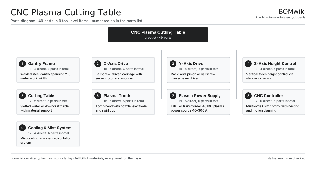
| # | Part | Qty | What it does |
|---|---|---|---|
| 1 | Gantry Frame 4 parts | 1× | Welded steel gantry spanning 2–5 meter work width |
| 2 | X-Axis Drive 5 parts | 1× | Ballscrew-driven carriage with servo motor and encoder |
| 3 | Y-Axis Drive 4 parts | 1× | Rack-and-pinion or ballscrew cross-beam drive |
| 4 | Z-Axis Height Control 4 parts | 1× | Vertical torch height control via stepper or servo |
| 5 | Cutting Table 5 parts | 1× | Slotted water or downdraft table with material support |
| 6 | Plasma Torch 5 parts | 1× | Torch head with nozzle, electrode, and swirl cup |
| 7 | Plasma Power Supply 5 parts | 1× | IGBT or transformer AC/DC plasma power source 40–300 A |
| 8 | CNC Controller 6 parts | 1× | Multi-axis CNC control with nesting and motion planning |
| 9 | Cooling & Mist System 4 parts | 1× | Mist cooling or water recirculation system |
3D model
No 3D model yet. Have a CAD file of this? Add a 3D model. STL renders right on this page; STEP, FreeCAD, and OpenSCAD sources are welcome too (openly licensed, like all 3D models on BOMwiki).
Build & assembly graph
expand / collapse · shared sub-assemblies converge · links to related products · est. labourTap an assembly to expand/collapse · tap a part to open it · use “Open page” for any node · drag to pan, scroll to zoom.
Bill of materials for CNC Plasma Cutting Table
9 top-level lines · 51 rows shown · 49 parts total · indented to 3 levels| # | Item / sub-assembly | Part no. | Qty/assy | Ext. qty | Parts | Type |
|---|---|---|---|---|---|---|
| 1 | Gantry Frame 4 parts | plasma-cutting-table-gantry-frame | 1× | 1 | 7 | assembly |
| 1.1 | Main Beam | plasma-cutting-table-main-beam | 1× | 1 | · | part |
| 1.2 | Gantry Legs | plasma-cutting-table-gantry-legs | 2× | 2 | · | part |
| 1.3 | Vertical Rail | plasma-cutting-table-vertical-rail | 2× | 2 | · | part |
| 1.4 | Fastener Set | fastener-set | 2× | 2 | · | part |
| 2 | X-Axis Drive 5 parts | plasma-cutting-table-x-axis-drive | 1× | 1 | 6 | assembly |
| 2.1 | X Servo Motor | plasma-cutting-table-x-servo-motor | 1× | 1 | · | part |
| 2.2 | X Ballscrew | plasma-cutting-table-x-ballscrew | 1× | 1 | · | part |
| 2.3 | X Linear Bearing | plasma-cutting-table-x-linear-bearing | 2× | 2 | · | part |
| 2.4 | X Coupling | plasma-cutting-table-x-coupling | 1× | 1 | · | part |
| 2.5 | Encoder | encoder | 1× | 1 | · | part |
| 3 | Y-Axis Drive 4 parts | plasma-cutting-table-y-axis-drive | 1× | 1 | 5 | assembly |
| 3.1 | Y Servo Motor | plasma-cutting-table-y-servo-motor | 1× | 1 | · | part |
| 3.2 | Y Drive Mechanism | plasma-cutting-table-y-drive-mechanism | 1× | 1 | · | part |
| 3.3 | Y Linear Bearing | plasma-cutting-table-y-linear-bearing | 2× | 2 | · | part |
| 3.4 | Y Coupling | plasma-cutting-table-y-coupling | 1× | 1 | · | part |
| 4 | Z-Axis Height Control 4 parts | plasma-cutting-table-z-axis-height | 1× | 1 | 5 | assembly |
| 4.1 | Z Stepper Motor | plasma-cutting-table-z-stepper-motor | 1× | 1 | · | part |
| 4.2 | Z Leadscrew | plasma-cutting-table-z-leadscrew | 1× | 1 | · | part |
| 4.3 | Z Linear Bearing | plasma-cutting-table-z-linear-bearing | 2× | 2 | · | part |
| 4.4 | Pressure Sensor | pressure-sensor | 1× | 1 | · | part |
| 5 | Cutting Table 5 parts | plasma-cutting-table-cutting-table | 1× | 1 | 5 | assembly |
| 5.1 | Table Base | plasma-cutting-table-table-base | 1× | 1 | · | part |
| 5.2 | Waste Grid | plasma-cutting-table-waste-grid | 1× | 1 | · | part |
| 5.3 | Water Tank | plasma-cutting-table-water-tank | 1× | 1 | · | part |
| 5.4 | Exhaust Plenum | plasma-cutting-table-exhaust-plenum | 1× | 1 | · | part |
| 5.5 | Fastener Set | fastener-set | 1× | 1 | · | part |
| 6 | Plasma Torch 5 parts | plasma-cutting-table-plasma-torch | 1× | 1 | 5 | assembly |
| 6.1 | Torch Body | plasma-cutting-table-torch-body | 1× | 1 | · | part |
| 6.2 | Cathode Electrode | plasma-cutting-table-cathode | 1× | 1 | · | part |
| 6.3 | Plasma Nozzle | plasma-cutting-table-nozzle | 1× | 1 | · | part |
| 6.4 | Swirl Cup | plasma-cutting-table-swirl-cup | 1× | 1 | · | part |
| 6.5 | Connector | connector | 1× | 1 | · | part |
| 7 | Plasma Power Supply 5 parts | plasma-cutting-table-power-supply | 1× | 1 | 6 | assembly |
| 7.1 | Power Transformer | plasma-cutting-table-power-transformer | 1× | 1 | · | part |
| 7.2 | IGBT Power Module | igbt-module | 2× | 2 | · | part |
| 7.3 | Output Filter | plasma-cutting-table-output-filter | 1× | 1 | · | part |
| 7.4 | Cooling Radiator | plasma-cutting-table-cooling-radiator | 1× | 1 | · | part |
| 7.5 | Power Supply | power-supply | 1× | 1 | · | part |
| 8 | CNC Controller 6 parts | plasma-cutting-table-cnc-controller | 1× | 1 | 6 | assembly |
| 8.1 | Motion Controller | plasma-cutting-table-motion-controller | 1× | 1 | · | part |
| 8.2 | X Servo Drive | plasma-cutting-table-servo-drive-x | 1× | 1 | · | part |
| 8.3 | Y Servo Drive | plasma-cutting-table-servo-drive-y | 1× | 1 | · | part |
| 8.4 | Stepper Driver | plasma-cutting-table-stepper-driver | 1× | 1 | · | part |
| 8.5 | Arc Voltage Monitor | plasma-cutting-table-arc-voltage-monitor | 1× | 1 | · | part |
| 8.6 | Power Supply | power-supply | 1× | 1 | · | part |
| 9 | Cooling & Mist System 4 parts | plasma-cutting-table-cooling-mist | 1× | 1 | 4 | assembly |
| 9.1 | Mist Pump | plasma-cutting-table-mist-pump | 1× | 1 | · | part |
| 9.2 | Mist Nozzle | plasma-cutting-table-mist-nozzle | 1× | 1 | · | part |
| 9.3 | Mist Tank | plasma-cutting-table-mist-tank | 1× | 1 | · | part |
| 9.4 | Coolant Filter | plasma-cutting-table-coolant-filter | 1× | 1 | · | part |
Related products
same domain, ranked by shared parts Bevel Gear Generator
201 parts · shares 1 with this page
Centering and Facing Machine
1,419 parts · shares 1 with this page
Bevel Gear Generator
201 parts · shares 1 with this page
Centering and Facing Machine
1,419 parts · shares 1 with this page
 Centerless Grinder
129 parts · shares 1 with this page
Centerless Grinder
129 parts · shares 1 with this page
 CNC Lathe
511 parts · shares 1 with this page
CNC Metal Spinning Machine
768 parts · shares 1 with this page
CNC Lathe
511 parts · shares 1 with this page
CNC Metal Spinning Machine
768 parts · shares 1 with this page
Sourcing: possible vendors
Browse the supplier directory → Prices, MOQ, and lead times are algorithmic estimates, not quotes, and not claims about these companies. Company mappings are curated by keyword; est. price band $10k–$1M. How estimates work| Vendor | HQ | Specialty | MOQ | Lead time |
|---|---|---|---|---|
|
🇩🇪DMG MORI
dmgmori.com ↗
|
Bielefeld, DE | Machine tools | 5 units | 12–20 wks |
|
🇯🇵Mazak
mazak.com ↗
|
Oguchi, JP | Machine tools | 5 units | 12–20 wks |
| haascnc.com ↗ | Oxnard, US | CNC machine tools | 5 units | 12–20 wks |
|
🇯🇵Okuma
okuma.com ↗
|
Niwa, JP | Machine tools | 5 units | 12–20 wks |
|
🇩🇪Trumpf
trumpf.com ↗
|
Ditzingen, DE | Laser & sheet-metal machines | 5 units | 12–20 wks |
1,434-word article