Hydraulic System
AssemblySupplies clamping force, injection velocity, and die cooling pressure with rapid response and high reliability. A full specification article for this item is being written. Meanwhile its bill of materials and connections are below.
Hydraulic System parts and their functions
7 top-level parts · 16 parts in total · full bill of materials below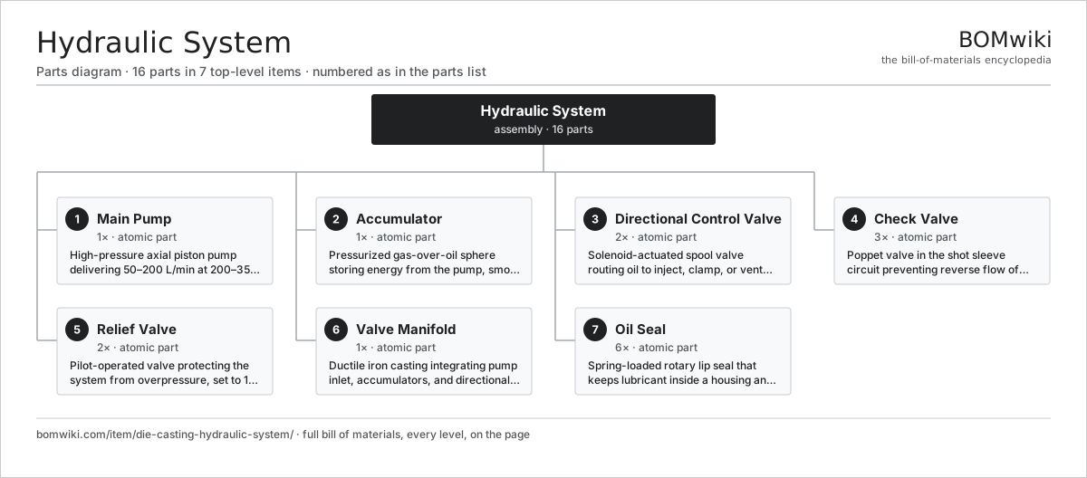
| # | Part | Qty | What it does |
|---|---|---|---|
| 1 | Main Pump | 1× | High-pressure axial piston pump delivering 50–200 L/min at 200–350 bar to the manifold. |
| 2 | Accumulator | 1× | Pressurized gas-over-oil sphere storing energy from the pump, smoothing pressure spikes during injection. |
| 3 | Directional Control Valve | 2× | Solenoid-actuated spool valve routing oil to inject, clamp, or vent circuits with millisecond response. |
| 4 | Check Valve | 3× | Poppet valve in the shot sleeve circuit preventing reverse flow of molten metal. |
| 5 | Relief Valve | 2× | Pilot-operated valve protecting the system from overpressure, set to 1.3× maximum working pressure. |
| 6 | Valve Manifold | 1× | Ductile iron casting integrating pump inlet, accumulators, and directional valves on one sandwich block. |
| 7 | Oil Seal | 6× | Spring-loaded rotary lip seal that keeps lubricant inside a housing and dirt out where a shaft passes through, sized to DIN 3760. |
3D model
No 3D model yet. Have a CAD file of this? Add a 3D model. STL renders right on this page; STEP, FreeCAD, and OpenSCAD sources are welcome too (openly licensed, like all 3D models on BOMwiki).
Build & assembly graph
expand / collapse · shared sub-assemblies converge · links to related products · est. labour
product / assembly
shared across products
atomic part
related product
Tap an assembly to expand/collapse · tap a part to open it · use “Open page” for any node · drag to pan, scroll to zoom.
Bill of materials for Hydraulic System
7 top-level lines · 7 rows shown · 16 parts total · indented to 3 levels| # | Item / sub-assembly | Part no. | Qty/assy | Ext. qty | Parts | Type |
|---|---|---|---|---|---|---|
| 1 | Main Pump | die-casting-main-pump | 1× | 1 | · | part |
| 2 | Accumulator | die-casting-pressure-accumulator | 1× | 1 | · | part |
| 3 | Directional Control Valve | die-casting-control-valve | 2× | 2 | · | part |
| 4 | Check Valve | die-casting-check-valve | 3× | 3 | · | part |
| 5 | Relief Valve | die-casting-relief-valve | 2× | 2 | · | part |
| 6 | Valve Manifold | die-casting-manifold-block | 1× | 1 | · | part |
| 7 | Oil Seal | oil-seal | 6× | 6 | · | part |
Something wrong in this list? Report a problem with this BOM.
Where the hydraulic system is used
1 product across 1 domain contain it, directly or inside a sub-assemblyUsed in 1 assembly
Sourcing: possible vendors
Browse the supplier directory → Prices, MOQ, and lead times are algorithmic estimates, not quotes, and not claims about these companies. Company mappings are curated by keyword; est. price band $5–$2k. How estimates work| Vendor | HQ | Specialty | MOQ | Lead time |
|---|---|---|---|---|
| kbl.co.in ↗ | Pune, IN | Pumps & fluid systems | 200 units | 6–10 wks |
| leo.com.cn ↗ | Taizhou, CN | Pumps | 200 units | 6–10 wks |
| shaktipumps.com ↗ | Pithampur, IN | Pumps | 200 units | 6–10 wks |
| cnppumps.com ↗ | Hangzhou, CN | Pumps | 200 units | 6–10 wks |
| rotopumps.com ↗ | Noida, IN | Pumps | 200 units | 6–10 wks |