Cast Film Extrusion Line
ProductOverview
A cast film line makes flat plastic film by extruding a wide thin curtain of melt through a slot die and quenching it against a polished water-cooled roll. Where a blown film line cools the melt in air, a cast line freezes it in milliseconds on chilled metal, which gives film with high clarity, tight gauge tolerance, and a smooth surface. The fast quench and high line speeds make it the preferred process for stretch wrap, cast polypropylene packaging film, hygiene backsheet, and release liner. The cost is that film width is fixed by the die, so changing width means changing deckles rather than turning a knob.
The line is a horizontal process. The Single-Screw Extruder melts and meters the resin into the Feedblock and Die, which spreads it into a wide curtain. The Chill Roll Stack freezes the curtain into film, with the Pinning System pinning it tight to the roll. The web then runs through the Edge Trim System, past the Thickness Gauge and the Corona Station, and onto the Turret Winder. The Control System holds the whole process, and the Machine Frame carries it.
Melting and metering
The Single-Screw Extruder melts the resin and delivers a steady high-pressure stream. Pellets and additives are blended by the Gravimetric Doser in the Feed Hopper, then drop through a cooled Feed Throat onto the Extruder Screw. That screw carries a Maddock mixing section because cast film shows every unmelted gel as a defect, so the melt must be fully homogeneous before it reaches the die. The Band Heater bands set the zone temperatures reported by each Thermocouple, the AC Drive Motor turns the screw through the Reduction Gearbox, and the melt passes a Screen Changer that strains gels through fine Filter Screen mesh. A Melt Pump then delivers a pulse-free flow, which matters more here than on most processes because gauge tolerance on cast film can be a few percent.
Forming the curtain
The Feedblock and Die turns the round melt stream into a wide flat sheet. When several extruders run, the Feedblock stacks their melt streams into the layer structure first, so a single die can produce a multilayer film with a sealant skin, a barrier core, and a print skin. The Flat Die uses a coat-hanger manifold that spreads the melt to an even flow across its full width, exiting through a slot whose Flexible Lip flexible lip is trimmed by a row of Die Lip Bolt bolts to fine-tune the thickness profile. A Deckle at each end sets the working width, and Die Heater cartridges hold the steel at melt temperature so flow does not freeze at the edges.
Quenching and pinning
The heart of a cast line is the quench. The melt curtain drops from the die onto the Primary Chill Roll, a mirror-finish chrome roll fed cold water through a Rotary Union from the Chiller Unit. The melt freezes against the roll in a fraction of a second, which locks in clarity by giving the polymer no time to crystallize coarsely. For the film to take the roll's smooth finish, no air can be trapped under it, so the Pinning System does the pinning: the Air Knife lays a thin air sheet that presses the curtain onto the roll, a Vacuum Chamber behind the contact line removes the boundary air, and an Edge Pinner holds down the slow-cooling edges. The web passes over the Secondary Chill Roll to finish cooling, then a Stripper Roll peels it cleanly off.
Trimming, measuring, and treating
The film comes off the rolls with thick beaded edges, so the Edge Trim System slits them off with a Trim Knife and pulls the strips away through a Trim Suction venturi to a Edge Granulator, which chops them into regrind that a Trim Blower returns to the hopper. The trimmed web crosses the Thickness Gauge, where a Gauge Scanner Head head traverses the width carrying a Gauge Source and Gauge Detector that read basis weight from radiation absorption, and the result feeds back to the die bolts so the profile stays flat to within a few percent. Film that will be printed or coated then runs through the Corona Station, where a Corona Electrode discharge over the Treater Roll raises the surface energy, and a Ozone Extractor removes the ozone the discharge makes.
Winding and control
The finished web reaches the Turret Winder, a turret design that winds onto a core and then transfers to a fresh core without stopping. The Turret Arm indexes a new Winder Spindle into place, the Cutoff Knife severs the web, and the Lay-On Roll presses the film to drive out trapped air while torque-driven Winder Motor units hold tension buffered by the Dancer Roll. The Control System ties everything together: a PLC sequences the line, a Variable Frequency Drive sets each motor speed, the Profile Controller manages the gauge map, and the operator works from the HMI Panel. The line is carried on a rigid Machine Frame whose Roll Stand stands hold the chill rolls parallel, guarded by Light Curtain beams at the operator side.
Materials, variants, and use
Cast lines run polypropylene and polyethylene most of all. Cast polypropylene film is clear and stiff for food and textile packaging; cast polyethylene stretch film is tough and clingy for pallet wrapping; and multilayer cast film makes hygiene backsheet, lamination film, and barrier packaging by combining sealant, barrier, and skin layers in one pass. Lines run from a single layer at moderate speed to nine layers at over 500 m/min on a wide die. Compared with the Blown Film Extrusion Line, cast film is clearer, flatter, and faster, and its layer structure is easier to control, but it cannot change width on the fly and its film is less balanced in strength because it is drawn mainly in one direction. Stretch wrap lines often add a downstream machine-direction orienter to pre-stretch the film before winding.
Cast Film Extrusion Line parts and their functions
10 top-level parts · 406 parts in total · full bill of materials below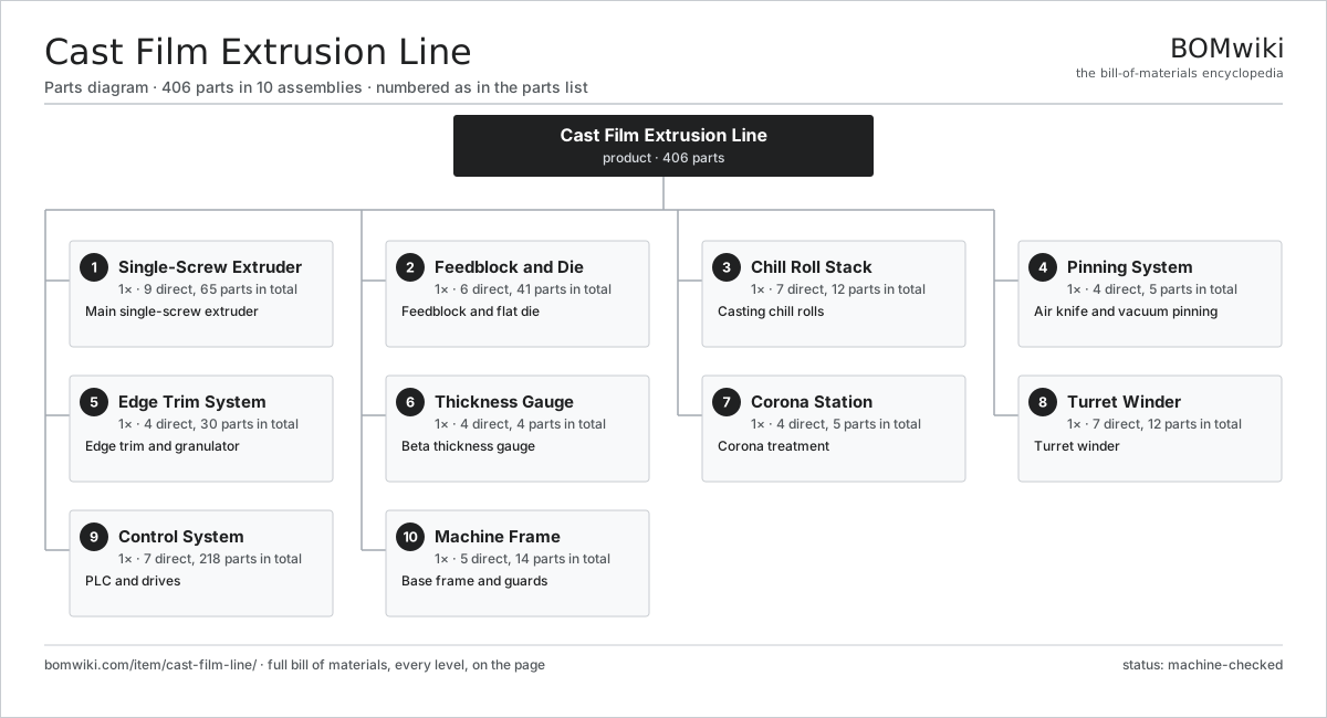
| # | Part | Qty | What it does |
|---|---|---|---|
| 1 | Single-Screw Extruder 9 parts | 1× | Main single-screw extruder |
| 2 | Feedblock and Die 6 parts | 1× | Feedblock and flat die |
| 3 | Chill Roll Stack 7 parts | 1× | Casting chill rolls |
| 4 | Pinning System 4 parts | 1× | Air knife and vacuum pinning |
| 5 | Edge Trim System 4 parts | 1× | Edge trim and granulator |
| 6 | Thickness Gauge 4 parts | 1× | Beta thickness gauge |
| 7 | Corona Station 4 parts | 1× | Corona treatment |
| 8 | Turret Winder 7 parts | 1× | Turret winder |
| 9 | Control System 7 parts | 1× | PLC and drives |
| 10 | Machine Frame 5 parts | 1× | Base frame and guards |
3D model
No 3D model yet. Have a CAD file of this? Add a 3D model — STL renders right on this page; STEP, FreeCAD, and OpenSCAD sources are welcome too (openly licensed, like all 3D models on BOMwiki).
Build & assembly graph
expand / collapse · shared sub-assemblies converge · links to related products · est. labourTap an assembly to expand/collapse · tap a part to open it · use “Open page” for any node · drag to pan, scroll to zoom.
Bill of materials for Cast Film Extrusion Line
10 top-level lines · 101 rows shown · 406 parts total · indented to 3 levels| # | Item / sub-assembly | Part no. | Qty/assy | Ext. qty | Parts | Type |
|---|---|---|---|---|---|---|
| 1 | Single-Screw Extruder 9 parts | cfl-extruder | 1× | 1 | 65 | assembly |
| 1.1 | Feed Hopper 3 parts | cfl-feed-hopper | 1× | 1 | 3 | assembly |
| 1.1.1 | Hopper Cone | cfl-hopper-cone | 1× | 1 | · | part |
| 1.1.2 | Gravimetric Doser | cfl-gravimetric-doser | 1× | 1 | · | part |
| 1.1.3 | Feed Throat | cfl-feed-throat | 1× | 1 | · | part |
| 1.2 | Extruder Barrel | cfl-barrel | 1× | 1 | · | part |
| 1.3 | Extruder Screw | cfl-screw | 1× | 1 | · | part |
| 1.4 | Band Heater | cfl-barrel-heater | 6× | 6 | · | part |
| 1.5 | Thermocouple | cfl-thermocouple | 6× | 6 | · | part |
| 1.6 | Reduction Gearbox 4 parts | cfl-gearbox | 1× | 1 | 9 | assembly |
| 1.6.1 | Helical Gear Pair | gear-pair | 2× | 2 | · | part |
| 1.6.2 | Gearbox Housing | gearbox-housing | 1× | 1 | · | part |
| 1.6.3 | Ball Bearing | ball-bearing | 4× | 4 | · | part |
| 1.6.4 | Oil Seal | oil-seal | 2× | 2 | · | part |
| 1.7 | AC Drive Motor 5 parts | cfl-drive-motor | 1× | 1 | 26 | assembly |
| 1.7.1 | Stator Assembly 3 parts + deeper › | stator-assembly | 1× | 1 | 3 | assembly |
| 1.7.2 | Rotor Assembly 4 parts + deeper › | rotor-assembly | 1× | 1 | 19 | assembly |
| 1.7.3 | Motor Housing | motor-housing | 1× | 1 | · | part |
| 1.7.4 | Ball Bearing | ball-bearing | 2× | 2 | · | part |
| 1.7.5 | Encoder | encoder | 1× | 1 | · | part |
| 1.8 | Screen Changer 3 parts | cfl-screen-changer | 1× | 1 | 7 | assembly |
| 1.8.1 | Breaker Plate | cfl-breaker-plate | 1× | 1 | · | part |
| 1.8.2 | Filter Screen | cfl-filter-screen | 4× | 4 | · | part |
| 1.8.3 | Changer Piston | cfl-changer-piston | 2× | 2 | · | part |
| 1.9 | Melt Pump 4 parts | cfl-melt-pump | 1× | 1 | 6 | assembly |
| 1.9.1 | Helical Gear Pair | gear-pair | 1× | 1 | · | part |
| 1.9.2 | Gearbox Housing | gearbox-housing | 1× | 1 | · | part |
| 1.9.3 | Ball Bearing | ball-bearing | 2× | 2 | · | part |
| 1.9.4 | Oil Seal | oil-seal | 2× | 2 | · | part |
| 2 | Feedblock and Die 6 parts | cfl-feedblock-die | 1× | 1 | 41 | assembly |
| 2.1 | Feedblock | cfl-feedblock | 1× | 1 | · | part |
| 2.2 | Flat Die | cfl-flat-die | 1× | 1 | · | part |
| 2.3 | Die Lip Bolt | cfl-die-bolt | 30× | 30 | · | part |
| 2.4 | Flexible Lip | cfl-flex-lip | 1× | 1 | · | part |
| 2.5 | Die Heater | cfl-die-heater | 6× | 6 | · | part |
| 2.6 | Deckle | cfl-deckle | 2× | 2 | · | part |
| 3 | Chill Roll Stack 7 parts | cfl-chill-roll-stack | 1× | 1 | 12 | assembly |
| 3.1 | Primary Chill Roll | cfl-primary-chill-roll | 1× | 1 | · | part |
| 3.2 | Secondary Chill Roll | cfl-secondary-chill-roll | 1× | 1 | · | part |
| 3.3 | Roll Drive | cfl-roll-drive | 2× | 2 | · | part |
| 3.4 | Chiller Unit | cfl-chiller-unit | 1× | 1 | · | part |
| 3.5 | Rotary Union | cfl-rotary-union | 2× | 2 | · | part |
| 3.6 | Ball Bearing | ball-bearing | 4× | 4 | · | part |
| 3.7 | Stripper Roll | cfl-stripper-roll | 1× | 1 | · | part |
| 4 | Pinning System 4 parts | cfl-vacuum-box | 1× | 1 | 5 | assembly |
| 4.1 | Air Knife | cfl-air-knife | 1× | 1 | · | part |
| 4.2 | Vacuum Chamber | cfl-vacuum-chamber | 1× | 1 | · | part |
| 4.3 | Vacuum Blower | cfl-vacuum-blower | 1× | 1 | · | part |
| 4.4 | Edge Pinner | cfl-edge-pinner | 2× | 2 | · | part |
| 5 | Edge Trim System 4 parts | cfl-edge-trim | 1× | 1 | 30 | assembly |
| 5.1 | Trim Knife | cfl-trim-knife | 2× | 2 | · | part |
| 5.2 | Trim Suction | cfl-trim-suction | 1× | 1 | · | part |
| 5.3 | Edge Granulator 3 parts | cfl-granulator | 1× | 1 | 26 | assembly |
| 5.3.1 | Granulator Rotor | cfl-granulator-rotor | 1× | 1 | · | part |
| 5.3.2 | Granulator Screen | cfl-granulator-screen | 1× | 1 | · | part |
| 5.3.3 | Servo Motor 4 parts + deeper › | servo-motor | 1× | 1 | 24 | assembly |
| 5.4 | Trim Blower | cfl-trim-blower | 1× | 1 | · | part |
| 6 | Thickness Gauge 4 parts | cfl-thickness-gauge | 1× | 1 | 4 | assembly |
| 6.1 | Gauge Scanner Head | cfl-gauge-scanner | 1× | 1 | · | part |
| 6.2 | Gauge Source | cfl-gauge-source | 1× | 1 | · | part |
| 6.3 | Gauge Detector | cfl-gauge-detector | 1× | 1 | · | part |
| 6.4 | Scanner Track | cfl-scanner-track | 1× | 1 | · | part |
| 7 | Corona Station 4 parts | cfl-corona-station | 1× | 1 | 5 | assembly |
| 7.1 | Corona Electrode | cfl-corona-electrode | 2× | 2 | · | part |
| 7.2 | Treater Roll | cfl-corona-roll | 1× | 1 | · | part |
| 7.3 | Corona Generator | cfl-corona-generator | 1× | 1 | · | part |
| 7.4 | Ozone Extractor | cfl-ozone-extractor | 1× | 1 | · | part |
| 8 | Turret Winder 7 parts | cfl-winder | 1× | 1 | 12 | assembly |
| 8.1 | Turret Arm | cfl-turret-arm | 1× | 1 | · | part |
| 8.2 | Winder Spindle | cfl-winder-spindle | 2× | 2 | · | part |
| 8.3 | Winder Motor | cfl-winder-motor | 2× | 2 | · | part |
| 8.4 | Lay-On Roll | cfl-lay-on-roll | 1× | 1 | · | part |
| 8.5 | Cutoff Knife | cfl-cutoff-knife | 1× | 1 | · | part |
| 8.6 | Dancer Roll | cfl-dancer-roll | 1× | 1 | · | part |
| 8.7 | Core Chuck | cfl-core-chuck | 4× | 4 | · | part |
| 9 | Control System 7 parts | cfl-control-system | 1× | 1 | 218 | assembly |
| 9.1 | PLC 4 parts | cfl-plc | 1× | 1 | 156 | assembly |
| 9.1.1 | Bare PCB | pcb-bare | 1× | 1 | · | part |
| 9.1.2 | Microcontroller | mcu | 1× | 1 | · | part |
| 9.1.3 | I/O Module | io-module | 4× | 4 | · | part |
| 9.1.4 | SMD Passive (R/C/L) | smd-passives | 150× | 150 | · | part |
| 9.2 | Variable Frequency Drive 4 parts | cfl-vfd | 5× | 5 | 5 | assembly |
| 9.2.1 | Bare PCB | pcb-bare | 1× | 5 | · | part |
| 9.2.2 | IGBT Power Module | igbt-module | 1× | 5 | · | part |
| 9.2.3 | DC-Link Capacitor | dc-link-cap | 2× | 10 | · | part |
| 9.2.4 | Microcontroller | mcu | 1× | 5 | · | part |
| 9.3 | HMI Panel 4 parts | cfl-hmi | 1× | 1 | 4 | assembly |
| 9.3.1 | LCD Panel | lcd-panel | 1× | 1 | · | part |
| 9.3.2 | Touch Digitizer | touch-digitizer | 1× | 1 | · | part |
| 9.3.3 | Bare PCB | pcb-bare | 1× | 1 | · | part |
| 9.3.4 | Microcontroller | mcu | 1× | 1 | · | part |
| 9.4 | Profile Controller | cfl-profile-controller | 1× | 1 | · | part |
| 9.5 | Power Supply | power-supply | 1× | 1 | · | part |
| 9.6 | Wire Bundle | wire-bundle | 1× | 1 | · | part |
| 9.7 | Connector | connector | 30× | 30 | · | part |
| 10 | Machine Frame 5 parts | cfl-machine-frame | 1× | 1 | 14 | assembly |
| 10.1 | Base Weldment | cfl-base-weldment | 1× | 1 | · | part |
| 10.2 | Roll Stand | cfl-roll-stand | 2× | 2 | · | part |
| 10.3 | Sheet Metal Panel | sheet-panel | 8× | 8 | · | part |
| 10.4 | Light Curtain | cfl-light-curtain | 2× | 2 | · | part |
| 10.5 | Fastener Set | fastener-set | 1× | 1 | · | part |
Related products
same domain, ranked by shared parts Twin-Screw Compounding Extruder
595 parts · shares 26 with this page
WPC Profile Extrusion Line
422 parts · shares 25 with this page
Blown Film Extrusion Line
436 parts · shares 25 with this page
Underwater Pelletizing System
290 parts · shares 23 with this page
Coil Coating Line
1,767 parts · shares 23 with this page
Acid Pickling Line
1,163 parts · shares 22 with this page
Twin-Screw Compounding Extruder
595 parts · shares 26 with this page
WPC Profile Extrusion Line
422 parts · shares 25 with this page
Blown Film Extrusion Line
436 parts · shares 25 with this page
Underwater Pelletizing System
290 parts · shares 23 with this page
Coil Coating Line
1,767 parts · shares 23 with this page
Acid Pickling Line
1,163 parts · shares 22 with this page
Sourcing: possible vendors
Prices, MOQ, and lead times are algorithmic estimates, not quotes, and not claims about these companies. Company mappings are curated by keyword; est. price band $5k–$2M. How estimates work| Vendor | HQ | Specialty | MOQ | Lead time |
|---|---|---|---|---|
| atlascopco.com ↗ | Stockholm, SE | Compressors & industrial | 10 units | 12–20 wks |
|
🇦🇹Andritz
andritz.com ↗
|
Graz, AT | Process plants & machinery | 10 units | 12–20 wks |
| buhlergroup.com ↗ | Uzwil, CH | Food & materials processing | 10 units | 12–20 wks |
| gea.com ↗ | Düsseldorf, DE | Process technology | 10 units | 12–20 wks |
| mhi.com ↗ | Tokyo, JP | Heavy machinery | 10 units | 12–20 wks |
1,051-word article