Automated Paint Spray Line
ProductOverview
An automated paint spray line carries finished or semi-finished parts continuously through cleaning, spray application, and curing without an operator touching the part between load and unload. Parts hang from an overhead Overhead Power-and-Free Conveyor and pass into a sealed Spray Booth Enclosure where robots and reciprocators apply liquid paint, then move on to a flash zone and a Flash-Off and Cure Oven oven that drives off solvent and crosslinks the film. Lines like this coat automotive bodies and bumpers, appliance cabinets, agricultural and construction machinery, steel furniture, and architectural extrusions.
The economics rest on three things: airflow that carries overspray away from the part and the painter, transfer efficiency that puts as much paint on the part as possible, and a controlled thermal profile that cures the film to specification. A modern line holds the booth at 20–26 °C and 60–75% relative humidity so paint viscosity and flash rate stay constant batch to batch.
How it works
A part is hung on a Part Carrier Trolley trolley at the load station. The trolley rolls on the lower free track while pusher dogs on the chain in the Power Track engage and advance it at the set line speed. The Caterpillar Drive Unit, a caterpillar drive with a Servo Motor on a variable-frequency drive, sets that speed, and a spring Take Up holds chain tension as the chain warms and stretches.
Inside the booth, vertical downdraft air at 0.4–0.6 m/s sweeps overspray and solvent vapor down through floor grating into a Extract Plenum. The air comes from the Air Supply House (AHU), where a Centrifugal Supply Fan pulls outside air through an Intake Filter bank, tempers it in the Direct-Fired Make-Up Air Heater, and pushes it through the ceiling Ceiling Filter media. A balanced Exhaust Extraction System system keeps the booth slightly negative relative to the surrounding plant so contaminated air never leaks outward.
Paint is applied by 6-axis robots and reciprocators. A 6-Axis Paint Robot positions a Rotary Bell Atomizer a fixed distance from the surface. The bell cup spins at 30,000–60,000 rpm, shearing the paint film at its edge into a fine mist; shaping air collapses that mist into a usable pattern. Charging the droplets with a High-Voltage Cascade at 60–100 kV makes them follow electric field lines onto the grounded part, including wrapping around to back surfaces, which is what lifts transfer efficiency to 70–90%.
Airflow and overspray capture
Overspray that misses the part has to be removed before the air recirculates or discharges. In a water-wash booth a Water Curtain sheets water down the back wall, and a Venturi Throat accelerates the air through a water column so paint solids are scrubbed out. A Wash Recirculation Pump recirculates the water, a Detackifier Doser adds chemistry that makes the paint non-sticky, and a Sludge Rake Conveyor skims the floated sludge to a bin. Dry booths replace this with replaceable cardboard or fiber filter banks; they cost less to run but generate more solid waste.
Filter and airflow health is watched continuously. A Pressure Sensor across each filter bank reports loading, and rising pressure drop signals a clogged stage before downdraft velocity falls out of tolerance.
Paint supply and color change
Paint reaches each atomizer through a circulating ring main so pigment stays in suspension. A Circulation Pump keeps the loop moving, a Fluid Regulator holds back-pressure steady, and a Flow Meter doses the volume the recipe calls for. When the line switches colors, the Color-Change Valve Stack selects the next paint, then a Solvent Flush Valve pushes solvent and air through the line to clear the old color in 20–45 seconds. Short color-change paths and small dead volumes cut both downtime and paint waste during changeover.
Curing
After application the part enters a flash-off zone that holds it warm enough to evaporate most of the solvent without skinning the surface. It then passes into the Oven Tunnel. An indirect-fired Indirect-Fired Oven Burner heats a stainless Heat Exchanger so combustion gas never contacts the wet film, and a Oven Recirculation Fan circulates the hot air to hold each zone uniform. Typical schedules run 140–200 °C for 20–40 minutes, set by the part metal mass and the paint chemistry. The oven walls are insulated double-skin panels to limit heat loss and keep shell temperatures safe.
Control and safety
A central Programmable Logic Controller sequences the conveyor, robots, fans, and oven, holding paint recipes and trip logic. Operators run the line from a Operator HMI Panel touchscreen. Because the booth atmosphere holds flammable solvent, safety is layered: a LEL Monitor trips the line if vapor approaches the lower explosive limit, airflow proving switches stop spraying if downdraft fails, and the Safety Relay and Interlock Panel ties e-stops and door interlocks into one safety circuit.
Variants and use
Configurations scale from single-robot booths coating a few parts per hour to full automotive topcoat lines running hundreds of bodies per hour with a dozen robots per booth. Powder-coat lines swap the wet atomizers for corona or tribo powder guns and add a powder recovery cyclone, but the conveyor, enclosure, airflow, and cure-oven architecture stay the same. Waterborne basecoat lines add humidity control and longer dehydration zones because water flashes more slowly than solvent.
Maintenance and failure modes
The most common faults are filter loading that starves downdraft velocity, bell bearing wear that shows up as runout and pattern distortion, and color-change cross-contamination from a worn Color Valve seat. Wash booths need detackifier dosing kept in range or the sludge fouls the Wash Recirculation Pump impeller and the venturi throats. On the thermal side, drift in the oven Temp Probe readings or a fouled heat exchanger leads to undercure, which appears downstream as poor adhesion or solvent pop. Scheduled bell rebuilds, filter changes on pressure-drop limits, and periodic conveyor chain lubrication and tension checks keep the line in spec.
Automated Paint Spray Line parts and their functions
9 top-level parts · 2,003 parts in total · full bill of materials below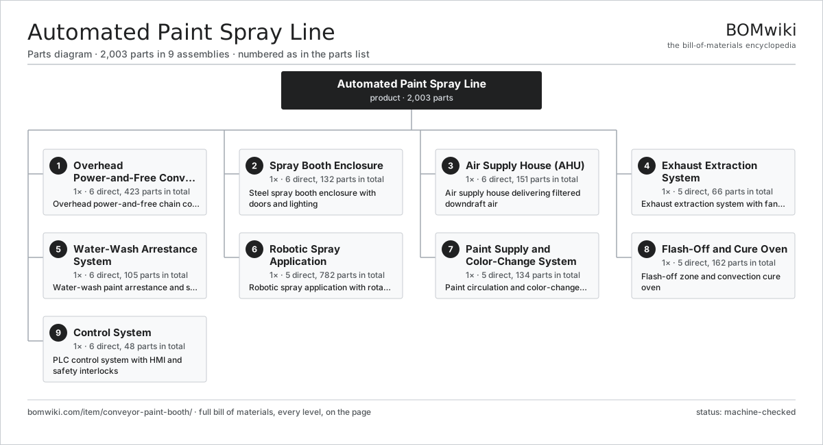
| # | Part | Qty | What it does |
|---|---|---|---|
| 1 | Overhead Power-and-Free Conveyor 6 parts | 1× | Overhead power-and-free chain conveyor moving parts on carriers |
| 2 | Spray Booth Enclosure 6 parts | 1× | Steel spray booth enclosure with doors and lighting |
| 3 | Air Supply House (AHU) 6 parts | 1× | Air supply house delivering filtered downdraft air |
| 4 | Exhaust Extraction System 5 parts | 1× | Exhaust extraction system with fans and stacks |
| 5 | Water-Wash Arrestance System 6 parts | 1× | Water-wash paint arrestance and sludge handling |
| 6 | Robotic Spray Application 5 parts | 1× | Robotic spray application with rotary bell atomizers |
| 7 | Paint Supply and Color-Change System 5 parts | 1× | Paint circulation and color-change system |
| 8 | Flash-Off and Cure Oven 5 parts | 1× | Flash-off zone and convection cure oven |
| 9 | Control System 6 parts | 1× | PLC control system with HMI and safety interlocks |
3D model
No 3D model yet. Have a CAD file of this? Add a 3D model — STL renders right on this page; STEP, FreeCAD, and OpenSCAD sources are welcome too (openly licensed, like all 3D models on BOMwiki).
Build & assembly graph
expand / collapse · shared sub-assemblies converge · links to related products · est. labourTap an assembly to expand/collapse · tap a part to open it · use “Open page” for any node · drag to pan, scroll to zoom.
Bill of materials for Automated Paint Spray Line
9 top-level lines · 150 rows shown · 2,003 parts total · indented to 3 levels| # | Item / sub-assembly | Part no. | Qty/assy | Ext. qty | Parts | Type |
|---|---|---|---|---|---|---|
| 1 | Overhead Power-and-Free Conveyor 6 parts | conveyor-paint-booth-conveyor | 1× | 1 | 423 | assembly |
| 1.1 | Power Track | conveyor-paint-booth-power-track | 1× | 1 | · | part |
| 1.2 | Free Track | conveyor-paint-booth-free-track | 1× | 1 | · | part |
| 1.3 | Drive Chain | conveyor-paint-booth-drive-chain | 1× | 1 | · | part |
| 1.4 | Caterpillar Drive Unit 7 parts | conveyor-paint-booth-drive-unit | 1× | 1 | 35 | assembly |
| 1.4.1 | Servo Motor 4 parts + deeper › | servo-motor | 1× | 1 | 24 | assembly |
| 1.4.2 | Gearbox Housing | gearbox-housing | 1× | 1 | · | part |
| 1.4.3 | Helical Gear Pair | gear-pair | 1× | 1 | · | part |
| 1.4.4 | Drive Sprocket | conveyor-paint-booth-drive-sprocket | 2× | 2 | · | part |
| 1.4.5 | Ball Bearing | ball-bearing | 4× | 4 | · | part |
| 1.4.6 | Oil Seal | oil-seal | 2× | 2 | · | part |
| 1.4.7 | Fastener Set | fastener-set | 1× | 1 | · | part |
| 1.5 | Take Up | conveyor-paint-booth-take-up | 1× | 1 | · | part |
| 1.6 | Part Carrier Trolley 5 parts | conveyor-paint-booth-carrier | 24× | 24 | 16 | assembly |
| 1.6.1 | Trolley Wheel | conveyor-paint-booth-trolley-wheel | 4× | 96 | · | part |
| 1.6.2 | Ball Bearing | ball-bearing | 4× | 96 | · | part |
| 1.6.3 | Hanger Bar | conveyor-paint-booth-hanger-bar | 1× | 24 | · | part |
| 1.6.4 | Part Hook | conveyor-paint-booth-part-hook | 6× | 144 | · | part |
| 1.6.5 | Fastener Set | fastener-set | 1× | 24 | · | part |
| 2 | Spray Booth Enclosure 6 parts | conveyor-paint-booth-enclosure | 1× | 1 | 132 | assembly |
| 2.1 | Sheet Metal Panel | sheet-panel | 28× | 28 | · | part |
| 2.2 | Plenum Ceiling | conveyor-paint-booth-plenum-ceiling | 1× | 1 | · | part |
| 2.3 | Personnel Door | conveyor-paint-booth-personnel-door | 2× | 2 | · | part |
| 2.4 | Booth Light Fixture 4 parts | conveyor-paint-booth-light-fixture | 12× | 12 | 5 | assembly |
| 2.4.1 | LED Tube | conveyor-paint-booth-led-tube | 2× | 24 | · | part |
| 2.4.2 | Light Glass | conveyor-paint-booth-light-glass | 1× | 12 | · | part |
| 2.4.3 | Power Supply | power-supply | 1× | 12 | · | part |
| 2.4.4 | Light Gasket | conveyor-paint-booth-light-gasket | 1× | 12 | · | part |
| 2.5 | Grating | conveyor-paint-booth-grating | 40× | 40 | · | part |
| 2.6 | Fastener Set | fastener-set | 1× | 1 | · | part |
| 3 | Air Supply House (AHU) 6 parts | conveyor-paint-booth-air-house | 1× | 1 | 151 | assembly |
| 3.1 | Centrifugal Supply Fan 5 parts | conveyor-paint-booth-supply-fan | 2× | 2 | 30 | assembly |
| 3.1.1 | Servo Motor 4 parts + deeper › | servo-motor | 1× | 2 | 24 | assembly |
| 3.1.2 | Drive Belt | drive-belt | 2× | 4 | · | part |
| 3.1.3 | Fan Wheel | conveyor-paint-booth-fan-wheel | 1× | 2 | · | part |
| 3.1.4 | Ball Bearing | ball-bearing | 2× | 4 | · | part |
| 3.1.5 | Fan Housing | conveyor-paint-booth-fan-housing | 1× | 2 | · | part |
| 3.2 | Intake Filter | conveyor-paint-booth-intake-filter | 16× | 16 | · | part |
| 3.3 | Ceiling Filter | conveyor-paint-booth-ceiling-filter | 60× | 60 | · | part |
| 3.4 | Direct-Fired Make-Up Air Heater 5 parts | conveyor-paint-booth-air-heater | 1× | 1 | 7 | assembly |
| 3.4.1 | Gas Burner | conveyor-paint-booth-gas-burner | 1× | 1 | · | part |
| 3.4.2 | Heating Element | heating-element | 2× | 2 | · | part |
| 3.4.3 | Gas Train | conveyor-paint-booth-gas-train | 1× | 1 | · | part |
| 3.4.4 | Flame Rod | conveyor-paint-booth-flame-rod | 1× | 1 | · | part |
| 3.4.5 | Pressure Sensor | pressure-sensor | 2× | 2 | · | part |
| 3.5 | Damper | conveyor-paint-booth-damper | 4× | 4 | · | part |
| 3.6 | Pressure Sensor | pressure-sensor | 4× | 4 | · | part |
| 4 | Exhaust Extraction System 5 parts | conveyor-paint-booth-exhaust | 1× | 1 | 66 | assembly |
| 4.1 | Extract Plenum | conveyor-paint-booth-extract-plenum | 1× | 1 | · | part |
| 4.2 | Centrifugal Extract Fan 5 parts | conveyor-paint-booth-extract-fan | 2× | 2 | 30 | assembly |
| 4.2.1 | Servo Motor 4 parts + deeper › | servo-motor | 1× | 2 | 24 | assembly |
| 4.2.2 | Drive Belt | drive-belt | 2× | 4 | · | part |
| 4.2.3 | Fan Wheel | conveyor-paint-booth-fan-wheel | 1× | 2 | · | part |
| 4.2.4 | Ball Bearing | ball-bearing | 2× | 4 | · | part |
| 4.2.5 | Fan Housing | conveyor-paint-booth-fan-housing | 1× | 2 | · | part |
| 4.3 | Exhaust Stack | conveyor-paint-booth-exhaust-stack | 2× | 2 | · | part |
| 4.4 | Exhaust Damper | conveyor-paint-booth-exhaust-damper | 2× | 2 | · | part |
| 4.5 | LEL Monitor | conveyor-paint-booth-lel-monitor | 1× | 1 | · | part |
| 5 | Water-Wash Arrestance System 6 parts | conveyor-paint-booth-arrestance | 1× | 1 | 105 | assembly |
| 5.1 | Water Curtain | conveyor-paint-booth-water-curtain | 1× | 1 | · | part |
| 5.2 | Venturi Throat | conveyor-paint-booth-venturi-throat | 4× | 4 | · | part |
| 5.3 | Wash Recirculation Pump 5 parts | conveyor-paint-booth-wash-pump | 2× | 2 | 29 | assembly |
| 5.3.1 | Servo Motor 4 parts + deeper › | servo-motor | 1× | 2 | 24 | assembly |
| 5.3.2 | Pump Impeller | conveyor-paint-booth-pump-impeller | 1× | 2 | · | part |
| 5.3.3 | Mechanical Seal | conveyor-paint-booth-mechanical-seal | 1× | 2 | · | part |
| 5.3.4 | Ball Bearing | ball-bearing | 2× | 4 | · | part |
| 5.3.5 | Pump Casing | conveyor-paint-booth-pump-casing | 1× | 2 | · | part |
| 5.4 | Sludge Tank | conveyor-paint-booth-sludge-tank | 1× | 1 | · | part |
| 5.5 | Sludge Rake Conveyor 5 parts | conveyor-paint-booth-sludge-rake | 1× | 1 | 40 | assembly |
| 5.5.1 | Servo Motor 4 parts + deeper › | servo-motor | 1× | 1 | 24 | assembly |
| 5.5.2 | Gearbox Housing | gearbox-housing | 1× | 1 | · | part |
| 5.5.3 | Helical Gear Pair | gear-pair | 1× | 1 | · | part |
| 5.5.4 | Rake Flight | conveyor-paint-booth-rake-flight | 12× | 12 | · | part |
| 5.5.5 | Ball Bearing | ball-bearing | 2× | 2 | · | part |
| 5.6 | Detackifier Doser | conveyor-paint-booth-detackifier-doser | 1× | 1 | · | part |
| 6 | Robotic Spray Application 5 parts | conveyor-paint-booth-application | 1× | 1 | 782 | assembly |
| 6.1 | 6-Axis Paint Robot 6 parts | conveyor-paint-booth-paint-robot | 4× | 4 | 162 | assembly |
| 6.1.1 | Servo Motor 4 parts + deeper › | servo-motor | 6× | 24 | 24 | assembly |
| 6.1.2 | Helical Gear Pair | gear-pair | 6× | 24 | · | part |
| 6.1.3 | Robot Arm Casting | conveyor-paint-booth-robot-arm-casting | 4× | 16 | · | part |
| 6.1.4 | Purge Unit | conveyor-paint-booth-purge-unit | 1× | 4 | · | part |
| 6.1.5 | Paint Hose Bundle | conveyor-paint-booth-paint-hose-bundle | 1× | 4 | · | part |
| 6.1.6 | Ball Bearing | ball-bearing | 6× | 24 | · | part |
| 6.2 | Vertical Reciprocator 5 parts | conveyor-paint-booth-reciprocator | 2× | 2 | 30 | assembly |
| 6.2.1 | Servo Motor 4 parts + deeper › | servo-motor | 1× | 2 | 24 | assembly |
| 6.2.2 | Ball Screw | ball-screw | 1× | 2 | · | part |
| 6.2.3 | Linear Guide Rail | linear-guide | 2× | 4 | · | part |
| 6.2.4 | Recip Carriage | conveyor-paint-booth-recip-carriage | 1× | 2 | · | part |
| 6.2.5 | Gun Mount Arm | conveyor-paint-booth-gun-mount-arm | 2× | 4 | · | part |
| 6.3 | Rotary Bell Atomizer 5 parts | conveyor-paint-booth-bell-atomizer | 6× | 6 | 5 | assembly |
| 6.3.1 | Bell Cup | conveyor-paint-booth-bell-cup | 1× | 6 | · | part |
| 6.3.2 | Air Turbine | conveyor-paint-booth-air-turbine | 1× | 6 | · | part |
| 6.3.3 | Shaping Air Ring | conveyor-paint-booth-shaping-air-ring | 1× | 6 | · | part |
| 6.3.4 | Paint Needle Valve | conveyor-paint-booth-paint-needle-valve | 1× | 6 | · | part |
| 6.3.5 | Speed Sensor | conveyor-paint-booth-speed-sensor | 1× | 6 | · | part |
| 6.4 | Automatic Air-Spray Gun 4 parts | conveyor-paint-booth-air-spray-gun | 4× | 4 | 5 | assembly |
| 6.4.1 | Spray Nozzle | conveyor-paint-booth-spray-nozzle | 1× | 4 | · | part |
| 6.4.2 | Gun Needle | conveyor-paint-booth-gun-needle | 1× | 4 | · | part |
| 6.4.3 | Air Valve | conveyor-paint-booth-air-valve | 1× | 4 | · | part |
| 6.4.4 | Coil Spring | coil-spring | 2× | 8 | · | part |
| 6.5 | High-Voltage Cascade 4 parts | conveyor-paint-booth-hv-cascade | 6× | 6 | 4 | assembly |
| 6.5.1 | Bare PCB | pcb-bare | 1× | 6 | · | part |
| 6.5.2 | Multiplier Stack | conveyor-paint-booth-multiplier-stack | 1× | 6 | · | part |
| 6.5.3 | HV Cable | conveyor-paint-booth-hv-cable | 1× | 6 | · | part |
| 6.5.4 | Current Limiter | conveyor-paint-booth-current-limiter | 1× | 6 | · | part |
| 7 | Paint Supply and Color-Change System 5 parts | conveyor-paint-booth-paint-supply | 1× | 1 | 134 | assembly |
| 7.1 | Circulation Pump | conveyor-paint-booth-circulation-pump | 2× | 2 | · | part |
| 7.2 | Color-Change Valve Stack 4 parts | conveyor-paint-booth-color-change-stack | 6× | 6 | 19 | assembly |
| 7.2.1 | Color Valve | conveyor-paint-booth-color-valve | 16× | 96 | · | part |
| 7.2.2 | Manifold Block | conveyor-paint-booth-manifold-block | 1× | 6 | · | part |
| 7.2.3 | O-Ring Set | oring-set | 1× | 6 | · | part |
| 7.2.4 | Pilot Valve Bank | conveyor-paint-booth-pilot-valve-bank | 1× | 6 | · | part |
| 7.3 | Fluid Regulator | conveyor-paint-booth-fluid-regulator | 6× | 6 | · | part |
| 7.4 | Flow Meter | conveyor-paint-booth-flow-meter | 6× | 6 | · | part |
| 7.5 | Solvent Flush Valve | conveyor-paint-booth-solvent-flush-valve | 6× | 6 | · | part |
| 8 | Flash-Off and Cure Oven 5 parts | conveyor-paint-booth-flash-cure | 1× | 1 | 162 | assembly |
| 8.1 | Flash Zone | conveyor-paint-booth-flash-zone | 1× | 1 | · | part |
| 8.2 | Oven Tunnel | conveyor-paint-booth-oven-tunnel | 1× | 1 | · | part |
| 8.3 | Indirect-Fired Oven Burner 5 parts | conveyor-paint-booth-oven-burner | 1× | 1 | 8 | assembly |
| 8.3.1 | Gas Burner | conveyor-paint-booth-gas-burner | 1× | 1 | · | part |
| 8.3.2 | Heat Exchanger | conveyor-paint-booth-heat-exchanger | 1× | 1 | · | part |
| 8.3.3 | Gas Train | conveyor-paint-booth-gas-train | 1× | 1 | · | part |
| 8.3.4 | Flame Rod | conveyor-paint-booth-flame-rod | 1× | 1 | · | part |
| 8.3.5 | Temp Probe | conveyor-paint-booth-temp-probe | 4× | 4 | · | part |
| 8.4 | Oven Recirculation Fan 4 parts | conveyor-paint-booth-recirc-fan | 4× | 4 | 29 | assembly |
| 8.4.1 | Servo Motor 4 parts + deeper › | servo-motor | 1× | 4 | 24 | assembly |
| 8.4.2 | Drive Belt | drive-belt | 2× | 8 | · | part |
| 8.4.3 | Fan Wheel | conveyor-paint-booth-fan-wheel | 1× | 4 | · | part |
| 8.4.4 | Ball Bearing | ball-bearing | 2× | 8 | · | part |
| 8.5 | Oven Panel | conveyor-paint-booth-oven-panel | 36× | 36 | · | part |
| 9 | Control System 6 parts | conveyor-paint-booth-controls | 1× | 1 | 48 | assembly |
| 9.1 | Programmable Logic Controller 5 parts | conveyor-paint-booth-plc | 1× | 1 | 15 | assembly |
| 9.1.1 | Bare PCB | pcb-bare | 3× | 3 | · | part |
| 9.1.2 | Microcontroller | mcu | 2× | 2 | · | part |
| 9.1.3 | SMD Passive (R/C/L) | smd-passives | 1× | 1 | · | part |
| 9.1.4 | Power Supply | power-supply | 1× | 1 | · | part |
| 9.1.5 | Connector | connector | 8× | 8 | · | part |
| 9.2 | Operator HMI Panel 4 parts | conveyor-paint-booth-hmi | 2× | 2 | 4 | assembly |
| 9.2.1 | LCD Panel | lcd-panel | 1× | 2 | · | part |
| 9.2.2 | Bare PCB | pcb-bare | 1× | 2 | · | part |
| 9.2.3 | Microcontroller | mcu | 1× | 2 | · | part |
| 9.2.4 | Power Supply | power-supply | 1× | 2 | · | part |
| 9.3 | Robot Controller | conveyor-paint-booth-robot-controller | 4× | 4 | · | part |
| 9.4 | Safety Relay and Interlock Panel 4 parts | conveyor-paint-booth-safety-relay-panel | 1× | 1 | 19 | assembly |
| 9.4.1 | Relay | relay | 8× | 8 | · | part |
| 9.4.2 | Estop Station | conveyor-paint-booth-estop-station | 6× | 6 | · | part |
| 9.4.3 | Door Interlock | conveyor-paint-booth-door-interlock | 4× | 4 | · | part |
| 9.4.4 | Wire Bundle | wire-bundle | 1× | 1 | · | part |
| 9.5 | IO Cabinet | conveyor-paint-booth-io-cabinet | 1× | 1 | · | part |
| 9.6 | Wire Bundle | wire-bundle | 1× | 1 | · | part |
Related products
same domain, ranked by shared parts Rubber Extrusion Line
524 parts · shares 28 with this page
Powder Coating Line
5,418 parts · shares 28 with this page
Shell Molding Machine
116 parts · shares 25 with this page
Rubber Extrusion Line
524 parts · shares 28 with this page
Powder Coating Line
5,418 parts · shares 28 with this page
Shell Molding Machine
116 parts · shares 25 with this page
 Continuous Galvanizing Line
1,296 parts · shares 26 with this page
Continuous Galvanizing Line
1,296 parts · shares 26 with this page
 Tensile Testing Machine
608 parts · shares 23 with this page
Hammer Mill
790 parts · shares 24 with this page
Tensile Testing Machine
608 parts · shares 23 with this page
Hammer Mill
790 parts · shares 24 with this page
Sourcing: possible vendors
Prices, MOQ, and lead times are algorithmic estimates, not quotes, and not claims about these companies. Company mappings are curated by keyword; est. price band $5k–$2M. How estimates work| Vendor | HQ | Specialty | MOQ | Lead time |
|---|---|---|---|---|
| atlascopco.com ↗ | Stockholm, SE | Compressors & industrial | 10 units | 12–20 wks |
|
🇦🇹Andritz
andritz.com ↗
|
Graz, AT | Process plants & machinery | 10 units | 12–20 wks |
| buhlergroup.com ↗ | Uzwil, CH | Food & materials processing | 10 units | 12–20 wks |
| gea.com ↗ | Düsseldorf, DE | Process technology | 10 units | 12–20 wks |
| mhi.com ↗ | Tokyo, JP | Heavy machinery | 10 units | 12–20 wks |
1,093-word article