Liquid Silicone Injection Machine
ProductOverview
A liquid silicone injection machine molds parts from two-part addition-cure liquid silicone rubber (LSR). Unlike thermoplastics that melt and freeze, LSR arrives as two low-viscosity liquids, compound A carrying the platinum catalyst and compound B carrying the cross-linker. The machine keeps both cold while metering and mixing them, injects the blend into a hot mold, and the heat vulcanizes the silicone into an elastic solid. The logic is inverted from thermoplastic molding: the Injection Unit stays cold and the Mold Heating System stays hot.
LSR parts are used where flexibility, biocompatibility and heat resistance matter: medical seals, baby bottle nipples, electrical insulators, gaskets, valves and overmolded grips. The Liquid Silicone Injection Machine runs as an unattended cell with automatic dosing from drums, valve-gated cold runners that leave no sprue, and full part traceability through the Control System.
Metering and mixing
The two compounds are drawn from 200 L drums by a pair of Drum Follower Pump units. Each uses a Follower Plate pressed down by a Ram Cylinder, wiping the high-viscosity material toward a Piston Transfer Pump so the drum empties cleanly. From there the A/B Metering Block holds the A to B ratio at 1:1 within 1 percent, because an off-ratio shot leaves the part either uncured and tacky or over-cross-linked and brittle.
If colored parts are needed, a Pigment Dosing Pump doses pigment paste at 0-5 percent into the stream. All three feeds meet at a Static Mixer Element, a disposable helical element that blends them with no moving parts and no dead spots where material could begin to cure. A Degassing Block pulls vacuum on the line to remove entrained air that would otherwise show as voids in the molded part. The mixed material then enters the Injection Barrel.
Injection unit
The Injection Unit is a reciprocating screw, but every surface that touches LSR is held below 40 C by the water-jacketed Injection Barrel. The Injection Screw has a low compression ratio and hard-chromed flights, because the silica filler in LSR is abrasive. During recovery the Screw Servo Motor turns the screw, drawing mixed material forward past the Non-Return Valve check ring. During injection the Injection Cylinder drives the screw axially, and the check ring seals so material flows out rather than back over the flights.
At the front the Cold Shutoff Nozzle is a needle shutoff design. The Nozzle Needle closes the melt channel between shots so the cold material cannot drool, and the Nozzle Cooling Block block keeps the Nozzle Body cold right up to the mold face. Injection pressures reach 2000 bar to fill thin medical-grade sections before any premature cure.
Cold runner and the heated mold
The biggest waste saving in LSR molding comes from the Cold Runner Block. The Cold Runner Manifold is insulated and held below 40 C by the Runner Cooling Circuit circuit, so material in the runner never cures. Each cavity is fed through a Valve Gate driven by a Gate Actuator: the gate opens to fill, then the needle closes and shears the material at the part surface. There is no sprue or runner to trim, scrap or recycle, and silicone scrap cannot be reground anyway.
Once the LSR reaches the cavity it must vulcanize. The Mold Heating System system embeds twelve or more Cartridge Heater elements in the mold plates and reads each zone with a Mold Thermocouple. A multi-loop Zone Temperature Controller holds the cavity at 160-220 C, and an Insulation Plate on each side stops that heat draining into the cold platens. Cure time scales with part wall thickness, typically 5-30 seconds.
Clamping and ejection
The Mold Clamping Unit holds the mold shut against injection pressure. A Toggle Linkage multiplies the stroke of the Clamp Cylinder into 50-300 tonne of clamp force across four Tie Bar columns. The Moving Platen travels on the tie bars between the Stationary Platen and the toggle, and the Crosshead drives the Toggle Link members through their over-center lock.
Because cured LSR is soft and tacky, ejection is gentle. The Ejector Assembly uses an Ejector Cylinder to push the Ejector Bar and Ejector Plate, often combined with air blow-off or a brush, so the flexible part peels off the core without tearing.
Hydraulics and control
A servo-driven Hydraulic Power Unit supplies the clamp, injection and ejector cylinders. The Hydraulic Pump is a variable-displacement unit driven by the Pump Drive Motor, drawing from the Oil Reservoir and feeding the actuators through a Valve Manifold of proportional and directional valves. An Hydraulic Accumulator buffers the brief high-flow demand of injection, an Oil Cooler holds oil at 45 C, and the Hydraulic Filter elements keep the oil clean.
The Control System ties it together. An PLC Controller with motion capability sequences dosing, injection, cure timing, clamp and ejection, while two Servo Drive units close the loop on the screw and metering servos. The operator works from the HMI Touch Panel touchscreen, storing recipes per mold. Everything sits in the Machine Frame and Guarding, whose Base Frame carries the loads and whose interlocked Safety Door guards stop the cycle if opened.
Variants
Smaller machines run from a 20 L pail with a single drum pump and a one or two cavity mold for prototyping. Production cells use 200 L drums, 16 or 32 cavity molds, and a robot to remove and sort parts. Full-electric machines replace the Hydraulic Power Unit with servo presses on clamp and injection, cutting energy use and oil contamination risk, which matters for cleanroom medical work. Self-lubricating LSR grades and two-shot machines that overmold LSR onto a thermoplastic substrate are common in connector and wearable production.
Liquid Silicone Injection Machine parts and their functions
8 top-level parts · 384 parts in total · full bill of materials below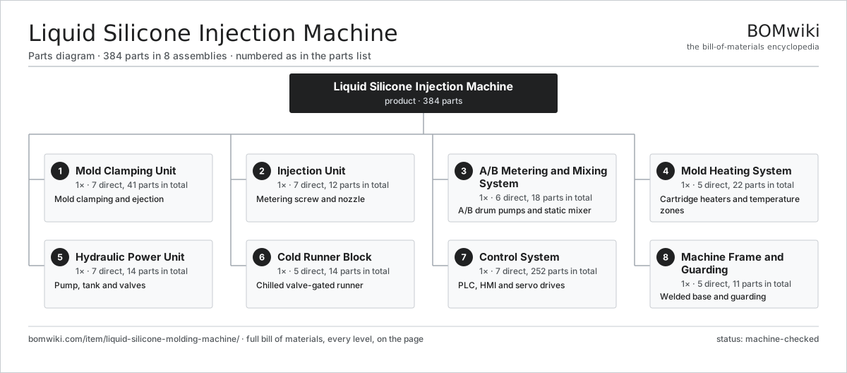
| # | Part | Qty | What it does |
|---|---|---|---|
| 1 | Mold Clamping Unit 7 parts | 1× | Mold clamping and ejection |
| 2 | Injection Unit 7 parts | 1× | Metering screw and nozzle |
| 3 | A/B Metering and Mixing System 6 parts | 1× | A/B drum pumps and static mixer |
| 4 | Mold Heating System 5 parts | 1× | Cartridge heaters and temperature zones |
| 5 | Hydraulic Power Unit 7 parts | 1× | Pump, tank and valves |
| 6 | Cold Runner Block 5 parts | 1× | Chilled valve-gated runner |
| 7 | Control System 7 parts | 1× | PLC, HMI and servo drives |
| 8 | Machine Frame and Guarding 5 parts | 1× | Welded base and guarding |
3D model
No 3D model yet. Have a CAD file of this? Add a 3D model — STL renders right on this page; STEP, FreeCAD, and OpenSCAD sources are welcome too (openly licensed, like all 3D models on BOMwiki).
Build & assembly graph
expand / collapse · shared sub-assemblies converge · links to related products · est. labourTap an assembly to expand/collapse · tap a part to open it · use “Open page” for any node · drag to pan, scroll to zoom.
Bill of materials for Liquid Silicone Injection Machine
8 top-level lines · 87 rows shown · 384 parts total · indented to 3 levels| # | Item / sub-assembly | Part no. | Qty/assy | Ext. qty | Parts | Type |
|---|---|---|---|---|---|---|
| 1 | Mold Clamping Unit 7 parts | lsr-clamp-unit | 1× | 1 | 41 | assembly |
| 1.1 | Stationary Platen | lsr-stationary-platen | 1× | 1 | · | part |
| 1.2 | Moving Platen | lsr-moving-platen | 1× | 1 | · | part |
| 1.3 | Tie Bar | lsr-tie-bar | 4× | 4 | · | part |
| 1.4 | Toggle Linkage 4 parts | lsr-toggle-linkage | 1× | 1 | 15 | assembly |
| 1.4.1 | Toggle Link | lsr-toggle-link | 4× | 4 | · | part |
| 1.4.2 | Crosshead | lsr-crosshead | 1× | 1 | · | part |
| 1.4.3 | Toggle Pin | lsr-toggle-pin | 6× | 6 | · | part |
| 1.4.4 | Ball Bearing | ball-bearing | 4× | 4 | · | part |
| 1.5 | Clamp Cylinder 5 parts | lsr-clamp-cylinder | 1× | 1 | 9 | assembly |
| 1.5.1 | Cylinder Tube | lsr-cylinder-tube | 1× | 1 | · | part |
| 1.5.2 | Cylinder Piston | lsr-cylinder-piston | 1× | 1 | · | part |
| 1.5.3 | Piston Rod | lsr-piston-rod | 1× | 1 | · | part |
| 1.5.4 | O-Ring Set | oring-set | 4× | 4 | · | part |
| 1.5.5 | Oil Seal | oil-seal | 2× | 2 | · | part |
| 1.6 | Ejector Assembly 3 parts | lsr-ejector-assembly | 1× | 1 | 3 | assembly |
| 1.6.1 | Ejector Cylinder | lsr-ejector-cylinder | 1× | 1 | · | part |
| 1.6.2 | Ejector Bar | lsr-ejector-bar | 1× | 1 | · | part |
| 1.6.3 | Ejector Plate | lsr-ejector-plate | 1× | 1 | · | part |
| 1.7 | Ball Bearing | ball-bearing | 8× | 8 | · | part |
| 2 | Injection Unit 7 parts | lsr-injection-unit | 1× | 1 | 12 | assembly |
| 2.1 | Injection Barrel | lsr-injection-barrel | 1× | 1 | · | part |
| 2.2 | Injection Screw | lsr-injection-screw | 1× | 1 | · | part |
| 2.3 | Non-Return Valve | lsr-non-return-valve | 1× | 1 | · | part |
| 2.4 | Cold Shutoff Nozzle 4 parts | lsr-injection-nozzle | 1× | 1 | 5 | assembly |
| 2.4.1 | Nozzle Body | lsr-nozzle-body | 1× | 1 | · | part |
| 2.4.2 | Nozzle Needle | lsr-nozzle-needle | 1× | 1 | · | part |
| 2.4.3 | Nozzle Cooling Block | lsr-nozzle-cooling | 1× | 1 | · | part |
| 2.4.4 | O-Ring Set | oring-set | 2× | 2 | · | part |
| 2.5 | Screw Servo Motor | lsr-injection-servo | 1× | 1 | · | part |
| 2.6 | Injection Cylinder | lsr-injection-cylinder | 1× | 1 | · | part |
| 2.7 | Ball Bearing | ball-bearing | 2× | 2 | · | part |
| 3 | A/B Metering and Mixing System 6 parts | lsr-dosing-system | 1× | 1 | 18 | assembly |
| 3.1 | Drum Follower Pump 4 parts | lsr-drum-pump | 2× | 2 | 6 | assembly |
| 3.1.1 | Follower Plate | lsr-follower-plate | 1× | 2 | · | part |
| 3.1.2 | Ram Cylinder | lsr-ram-cylinder | 1× | 2 | · | part |
| 3.1.3 | Piston Transfer Pump | lsr-piston-pump | 1× | 2 | · | part |
| 3.1.4 | O-Ring Set | oring-set | 3× | 6 | · | part |
| 3.2 | A/B Metering Block | lsr-metering-pump | 1× | 1 | · | part |
| 3.3 | Pigment Dosing Pump | lsr-color-pump | 1× | 1 | · | part |
| 3.4 | Static Mixer Element | lsr-static-mixer | 1× | 1 | · | part |
| 3.5 | Degassing Block | lsr-degassing-block | 1× | 1 | · | part |
| 3.6 | Pressure Sensor | pressure-sensor | 2× | 2 | · | part |
| 4 | Mold Heating System 5 parts | lsr-mold-heating | 1× | 1 | 22 | assembly |
| 4.1 | Cartridge Heater | lsr-cartridge-heater | 12× | 12 | · | part |
| 4.2 | Mold Thermocouple | lsr-thermocouple | 6× | 6 | · | part |
| 4.3 | Zone Temperature Controller | lsr-zone-controller | 1× | 1 | · | part |
| 4.4 | Insulation Plate | lsr-insulation-plate | 2× | 2 | · | part |
| 4.5 | Heater Terminal Box | lsr-heater-terminal-box | 1× | 1 | · | part |
| 5 | Hydraulic Power Unit 7 parts | lsr-hydraulic-power-unit | 1× | 1 | 14 | assembly |
| 5.1 | Hydraulic Pump | lsr-hydraulic-pump | 1× | 1 | · | part |
| 5.2 | Pump Drive Motor | lsr-pump-motor | 1× | 1 | · | part |
| 5.3 | Oil Reservoir | lsr-oil-tank | 1× | 1 | · | part |
| 5.4 | Valve Manifold 3 parts | lsr-valve-manifold | 1× | 1 | 7 | assembly |
| 5.4.1 | Proportional Valve | lsr-proportional-valve | 2× | 2 | · | part |
| 5.4.2 | Directional Valve | lsr-directional-valve | 4× | 4 | · | part |
| 5.4.3 | Relief Valve | lsr-relief-valve | 1× | 1 | · | part |
| 5.5 | Oil Cooler | lsr-oil-cooler | 1× | 1 | · | part |
| 5.6 | Hydraulic Filter | lsr-oil-filter | 2× | 2 | · | part |
| 5.7 | Hydraulic Accumulator | lsr-accumulator | 1× | 1 | · | part |
| 6 | Cold Runner Block 5 parts | lsr-cold-runner | 1× | 1 | 14 | assembly |
| 6.1 | Cold Runner Manifold | lsr-runner-manifold | 1× | 1 | · | part |
| 6.2 | Valve Gate | lsr-valve-gate | 4× | 4 | · | part |
| 6.3 | Runner Cooling Circuit | lsr-runner-cooling | 1× | 1 | · | part |
| 6.4 | Gate Actuator | lsr-gate-actuator | 4× | 4 | · | part |
| 6.5 | O-Ring Set | oring-set | 4× | 4 | · | part |
| 7 | Control System 7 parts | lsr-control-system | 1× | 1 | 252 | assembly |
| 7.1 | PLC Controller 3 parts | lsr-plc | 1× | 1 | 143 | assembly |
| 7.1.1 | Bare PCB | pcb-bare | 1× | 1 | · | part |
| 7.1.2 | Microcontroller | mcu | 2× | 2 | · | part |
| 7.1.3 | SMD Passive (R/C/L) | smd-passives | 140× | 140 | · | part |
| 7.2 | HMI Touch Panel 4 parts | lsr-hmi | 1× | 1 | 93 | assembly |
| 7.2.1 | LCD Panel | lcd-panel | 1× | 1 | · | part |
| 7.2.2 | Bare PCB | pcb-bare | 1× | 1 | · | part |
| 7.2.3 | Microcontroller | mcu | 1× | 1 | · | part |
| 7.2.4 | SMD Passive (R/C/L) | smd-passives | 90× | 90 | · | part |
| 7.3 | Servo Drive | lsr-servo-drive | 2× | 2 | · | part |
| 7.4 | Power Supply | power-supply | 1× | 1 | · | part |
| 7.5 | I/O Module | lsr-io-module | 2× | 2 | · | part |
| 7.6 | Relay | relay | 10× | 10 | · | part |
| 7.7 | Control Cabinet | lsr-control-cabinet | 1× | 1 | · | part |
| 8 | Machine Frame and Guarding 5 parts | lsr-machine-frame | 1× | 1 | 11 | assembly |
| 8.1 | Base Frame | lsr-base-frame | 1× | 1 | · | part |
| 8.2 | Safety Door | lsr-safety-door | 2× | 2 | · | part |
| 8.3 | Leveling Foot | lsr-leveling-foot | 6× | 6 | · | part |
| 8.4 | Drip Tray | lsr-drip-tray | 1× | 1 | · | part |
| 8.5 | Fastener Set | fastener-set | 1× | 1 | · | part |
Related products
same domain, ranked by shared parts Reaction Injection Molding Machine
457 parts · shares 26 with this page
Reaction Injection Molding Machine
457 parts · shares 26 with this page
 Stretch Blow Molding Machine
460 parts · shares 14 with this page
Automated Paint Spray Line
2,003 parts · shares 8 with this page
Coil Coating Line
1,767 parts · shares 8 with this page
Gravimetric Plastics Blender
139 parts · shares 8 with this page
Hammer Mill
790 parts · shares 8 with this page
Stretch Blow Molding Machine
460 parts · shares 14 with this page
Automated Paint Spray Line
2,003 parts · shares 8 with this page
Coil Coating Line
1,767 parts · shares 8 with this page
Gravimetric Plastics Blender
139 parts · shares 8 with this page
Hammer Mill
790 parts · shares 8 with this page
Sourcing: possible vendors
Prices, MOQ, and lead times are algorithmic estimates, not quotes, and not claims about these companies. Company mappings are curated by keyword; est. price band $5k–$2M. How estimates work| Vendor | HQ | Specialty | MOQ | Lead time |
|---|---|---|---|---|
| atlascopco.com ↗ | Stockholm, SE | Compressors & industrial | 10 units | 12–20 wks |
|
🇦🇹Andritz
andritz.com ↗
|
Graz, AT | Process plants & machinery | 10 units | 12–20 wks |
| buhlergroup.com ↗ | Uzwil, CH | Food & materials processing | 10 units | 12–20 wks |
| gea.com ↗ | Düsseldorf, DE | Process technology | 10 units | 12–20 wks |
| mhi.com ↗ | Tokyo, JP | Heavy machinery | 10 units | 12–20 wks |
1,001-word article