Electrocoating Line
ProductOverview
An electrocoating line, also called an e-coat or CED line, deposits a uniform paint film on metal parts by passing direct current between the part and an anode while the part is immersed in a waterborne paint bath. In a cathodic system the part is the cathode: the applied voltage drives charged paint particles out of the bath and onto every wetted surface, including recesses and box sections that spray painting cannot reach. The deposited film is self-limiting, so once a area is coated its resistance rises and deposition shifts to bare metal, which gives an even thickness across complex shapes. E-coat is the standard primer for automobile bodies, chassis parts, appliances, fasteners and agricultural equipment because it gives consistent corrosion protection at low paint waste.
A complete line is a sequence of process tanks and an oven linked by an overhead conveyor. Parts hang on racks, pass through Pretreatment Stage Tunnel to clean and chemically prepare the steel, get rinsed, are dipped in the Electrodeposition Dip Tank, rinsed again to recover drag-out paint, and then cured in the Bake and Cure Oven. Bath chemistry, voltage and oven temperature are held within tight bands by the Line Control System.
How it works
Cleaned and phosphated parts enter the dip tank and are connected to the negative terminal through the Electrical Contact Shoe on each rack. The DC Rectifier Power Supply ramps DC from zero to a setpoint between 200 and 400 V over several seconds to avoid gassing and film rupture. Paint resin in the bath carries a positive charge; under the field it migrates to the cathode and coagulates into an insoluble film. Because the film insulates the surface, current naturally redistributes to uncoated metal until the whole part reaches the target thickness of 15-35 microns. Coating takes 120-180 seconds.
The chemistry produces acid at the anodes. To keep bath pH in the 5.8-6.3 band, the anodes sit inside Anolyte Cell units bounded by an ion-exchange Anode Ion-Exchange Membrane. Acid passes through the membrane into the anolyte loop and is bled off, while the paint resin stays in the main bath. After the dip the part still carries loose, uncured paint on its surface; this drag-out is recovered in the post-rinse using ultrafiltration permeate so almost none of the paint is lost.
Pretreatment
Adhesion and corrosion resistance depend on what happens before the paint. The pretreatment tunnel runs the part through alkaline degrease at 55-65 C in the Alkaline Degrease Tank, two or more cascade water rinses, and a conversion stage in the Conversion Coating Tank. Older lines use zinc phosphate, which grows a crystalline layer that anchors the paint; newer lines use thin-film zirconium oxide, which uses less energy and produces no heavy-metal sludge. Each stage is fed by a spray pump and risers carrying spray nozzles, or by full immersion in a dunk tank. Bath strength is held by metering pumps on the dosing skid that read conductivity and pH and inject cleaner or conversion chemistry as the bath is consumed. Sludge from the phosphate stage settles in a cone and is filtered out so it does not redeposit on parts.
Paint circulation and ultrafiltration
The dip tank bath must move constantly or the paint solids settle and the film goes uneven. Several large circulation pumps turn the tank over six to eight times per hour and push the bath through bag filters that catch dirt and gel. A side loop runs the bath through an Ultrafiltration Module, a tubular membrane that lets clean water and small ions pass as permeate while holding back the paint resin. The permeate, low in solids, is sprayed on parts in the Post Electrocoat Rinse to wash off loose paint; that rinse drains back to the bath, so the recovered solids return to use. This closed loop is why e-coat reaches 95-99% transfer efficiency, far above spray painting.
Cure oven
After the final rinse the wet film must be dried and cross-linked. The oven starts with an infrared Infrared Flash-Off Zone that flashes off surface water quickly so it does not blister the film, using quartz Heating Element emitters. Parts then pass through gas-fired convection zones where a Oven Recirculation Fan blows air at 180 C across the work. The film must reach a metal temperature of 160-190 C and hold it for 18-25 minutes for the resin to cure fully. Thermocouples in each zone and a data logger record the profile so undercure or burn-off can be caught. Solvent and water vapor leave through an exhaust fan to a thermal abatement stack.
Variants and use
Lines are built around the part mix. A high-volume automotive line uses a continuous conveyor and a dip tank large enough to submerge a full body shell. Job-shop and fastener lines often use a programmed-hoist transport that lowers a rack straight down into each tank, which suits small batches and frequent color or chemistry changes. Bath chemistry splits into cathodic epoxy for primer under topcoat and cathodic acrylic where the e-coat is the visible finish and must resist sunlight. Throughput on a typical line runs 30-60 racks per hour at a conveyor speed of 1.5-4.0 m/min.
Failures and maintenance
The common faults are chemistry faults. If bath pH drifts because the Anolyte Recirculation System bleed is undersized or a membrane fails, the paint can become unstable and roughen. Low bath solids starve the film and give thin, porous coating; high solids cause runs and gas pinholes. Rectifier ripple from a worn output choke produces a streaky film, so the DC output is checked with the bath under load. Contact shoes and rack hooks burn and lose conductivity over time, which leaves uncoated patches, so they are cleaned or replaced on a schedule. In the oven, a fouled recirculation fan bearing or a drifting burner can pull cure temperature below spec and let corrosion through in salt-spray testing. Routine work centers on filter changes, membrane cleaning, dosing calibration and oven profile checks.
Electrocoating Line parts and their functions
10 top-level parts · 2,977 parts in total · full bill of materials below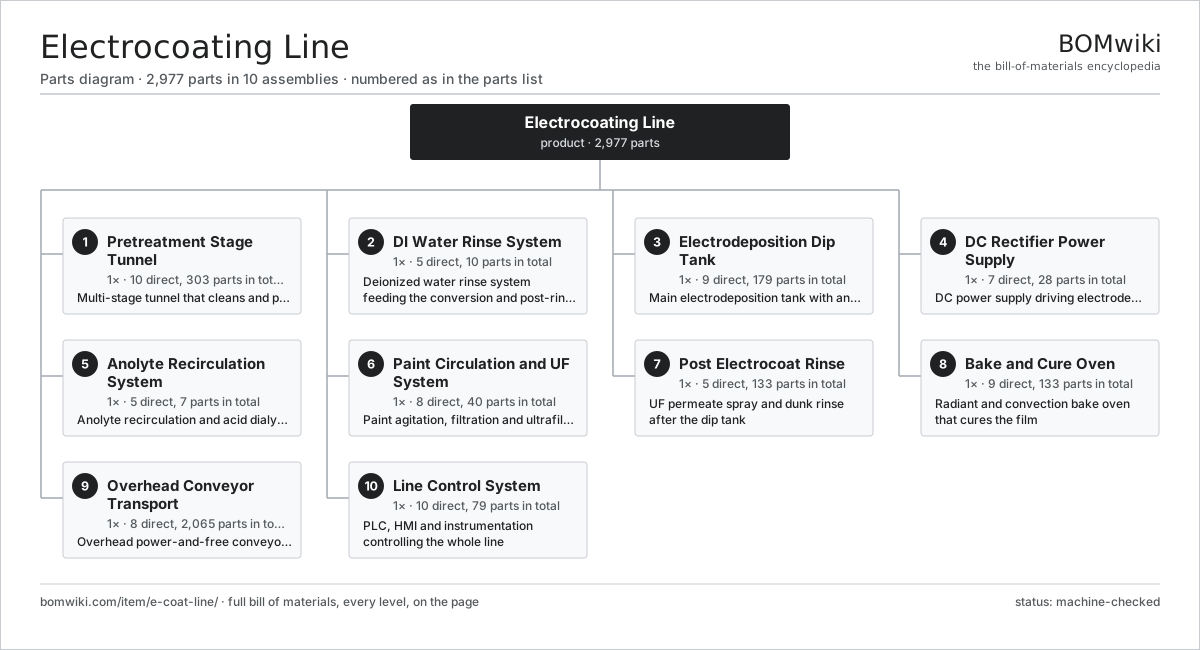
| # | Part | Qty | What it does |
|---|---|---|---|
| 1 | Pretreatment Stage Tunnel 10 parts | 1× | Multi-stage tunnel that cleans and phosphates parts before paint |
| 2 | DI Water Rinse System 5 parts | 1× | Deionized water rinse system feeding the conversion and post-rinse stages |
| 3 | Electrodeposition Dip Tank 9 parts | 1× | Main electrodeposition tank with anolyte cells and membranes |
| 4 | DC Rectifier Power Supply 7 parts | 1× | DC power supply driving electrodeposition |
| 5 | Anolyte Recirculation System 5 parts | 1× | Anolyte recirculation and acid dialysis loop |
| 6 | Paint Circulation and UF System 8 parts | 1× | Paint agitation, filtration and ultrafiltration loop |
| 7 | Post Electrocoat Rinse 5 parts | 1× | UF permeate spray and dunk rinse after the dip tank |
| 8 | Bake and Cure Oven 9 parts | 1× | Radiant and convection bake oven that cures the film |
| 9 | Overhead Conveyor Transport 8 parts | 1× | Overhead power-and-free conveyor carrying part racks |
| 10 | Line Control System 10 parts | 1× | PLC, HMI and instrumentation controlling the whole line |
3D model
No 3D model yet. Have a CAD file of this? Add a 3D model — STL renders right on this page; STEP, FreeCAD, and OpenSCAD sources are welcome too (openly licensed, like all 3D models on BOMwiki).
Build & assembly graph
expand / collapse · shared sub-assemblies converge · links to related products · est. labourTap an assembly to expand/collapse · tap a part to open it · use “Open page” for any node · drag to pan, scroll to zoom.
Bill of materials for Electrocoating Line
10 top-level lines · 132 rows shown · 2,977 parts total · indented to 3 levels| # | Item / sub-assembly | Part no. | Qty/assy | Ext. qty | Parts | Type |
|---|---|---|---|---|---|---|
| 1 | Pretreatment Stage Tunnel 10 parts | e-coat-line-pretreatment | 1× | 1 | 303 | assembly |
| 1.1 | Alkaline Degrease Tank 6 parts | e-coat-line-degrease-tank | 1× | 1 | 21 | assembly |
| 1.1.1 | Process Tank Shell | e-coat-line-tank-shell | 1× | 1 | · | part |
| 1.1.2 | Heating Element | heating-element | 4× | 4 | · | part |
| 1.1.3 | Belt Oil Skimmer | e-coat-line-oil-skimmer | 1× | 1 | · | part |
| 1.1.4 | Circulation Pump | e-coat-line-circulation-pump | 1× | 1 | · | part |
| 1.1.5 | Liquid Eductor | e-coat-line-eductor | 12× | 12 | · | part |
| 1.1.6 | Pressure Sensor | pressure-sensor | 2× | 2 | · | part |
| 1.2 | Cascade Rinse Stage | e-coat-line-spray-rinse-stage | 2× | 2 | · | part |
| 1.3 | Conversion Coating Tank 6 parts | e-coat-line-phosphate-tank | 1× | 1 | 8 | assembly |
| 1.3.1 | Process Tank Shell | e-coat-line-tank-shell | 1× | 1 | · | part |
| 1.3.2 | Circulation Pump | e-coat-line-circulation-pump | 1× | 1 | · | part |
| 1.3.3 | Bag Filter Housing | e-coat-line-bag-filter | 2× | 2 | · | part |
| 1.3.4 | Sludge Settling Cone | e-coat-line-sludge-cone | 1× | 1 | · | part |
| 1.3.5 | Heating Element | heating-element | 2× | 2 | · | part |
| 1.3.6 | Pressure Sensor | pressure-sensor | 1× | 1 | · | part |
| 1.4 | Chemical Dosing Skid 4 parts | e-coat-line-conversion-dosing | 1× | 1 | 11 | assembly |
| 1.4.1 | Diaphragm Dosing Pump | e-coat-line-dosing-pump | 4× | 4 | · | part |
| 1.4.2 | Additive Day Tank | e-coat-line-day-tank | 4× | 4 | · | part |
| 1.4.3 | Bath Analysis Probe | e-coat-line-titration-probe | 2× | 2 | · | part |
| 1.4.4 | Fastener Set | fastener-set | 1× | 1 | · | part |
| 1.5 | Spray Pump | e-coat-line-spray-pump | 4× | 4 | · | part |
| 1.6 | Spray Riser | e-coat-line-spray-riser | 8× | 8 | · | part |
| 1.7 | Spray Nozzle | e-coat-line-spray-nozzle | 240× | 240 | · | part |
| 1.8 | Bag Filter Housing | e-coat-line-bag-filter | 6× | 6 | · | part |
| 1.9 | Stage Heat Exchanger | e-coat-line-stage-heat-exchanger | 2× | 2 | · | part |
| 1.10 | Pretreatment Tunnel Enclosure | e-coat-line-tunnel-enclosure | 1× | 1 | · | part |
| 2 | DI Water Rinse System 5 parts | e-coat-line-di-rinse | 1× | 1 | 10 | assembly |
| 2.1 | Mixed-Bed DI Column | e-coat-line-di-column | 2× | 2 | · | part |
| 2.2 | DI Storage Tank | e-coat-line-di-storage-tank | 1× | 1 | · | part |
| 2.3 | Circulation Pump | e-coat-line-circulation-pump | 2× | 2 | · | part |
| 2.4 | Conductivity Cell | e-coat-line-conductivity-cell | 3× | 3 | · | part |
| 2.5 | Cartridge Filter | e-coat-line-cartridge-filter | 2× | 2 | · | part |
| 3 | Electrodeposition Dip Tank 9 parts | e-coat-line-dip-tank | 1× | 1 | 179 | assembly |
| 3.1 | Process Tank Shell | e-coat-line-tank-shell | 1× | 1 | · | part |
| 3.2 | Anolyte Cell 4 parts | e-coat-line-anolyte-cell | 24× | 24 | 4 | assembly |
| 3.2.1 | Anode Ion-Exchange Membrane | e-coat-line-anode-membrane | 1× | 24 | · | part |
| 3.2.2 | Anode Electrode | e-coat-line-electrode | 1× | 24 | · | part |
| 3.2.3 | Anolyte Cell Housing | e-coat-line-cell-housing | 1× | 24 | · | part |
| 3.2.4 | O-Ring Set | oring-set | 1× | 24 | · | part |
| 3.3 | Anode Ion-Exchange Membrane | e-coat-line-anode-membrane | 24× | 24 | · | part |
| 3.4 | Anode Electrode | e-coat-line-electrode | 24× | 24 | · | part |
| 3.5 | DC Busbar | e-coat-line-busbar | 4× | 4 | · | part |
| 3.6 | Bath Overflow Weir | e-coat-line-overflow-weir | 2× | 2 | · | part |
| 3.7 | Bath Heat Exchanger | e-coat-line-tank-heat-exchanger | 2× | 2 | · | part |
| 3.8 | Anolyte Cell Fitting | e-coat-line-anolyte-cell-feed | 24× | 24 | · | part |
| 3.9 | Pressure Sensor | pressure-sensor | 2× | 2 | · | part |
| 4 | DC Rectifier Power Supply 7 parts | e-coat-line-rectifier | 1× | 1 | 28 | assembly |
| 4.1 | Power Supply | power-supply | 1× | 1 | · | part |
| 4.2 | Rectifier Transformer | e-coat-line-rectifier-transformer | 1× | 1 | · | part |
| 4.3 | DC Output Choke | e-coat-line-output-choke | 1× | 1 | · | part |
| 4.4 | DC Output Contactor | e-coat-line-dc-contactor | 2× | 2 | · | part |
| 4.5 | Cooling Fan Unit 3 parts | e-coat-line-cooling-fan | 4× | 4 | 4 | assembly |
| 4.5.1 | Fan Impeller | e-coat-line-fan-impeller | 1× | 4 | · | part |
| 4.5.2 | Fan Motor | e-coat-line-fan-motor | 1× | 4 | · | part |
| 4.5.3 | Ball Bearing | ball-bearing | 2× | 8 | · | part |
| 4.6 | Rectifier Cabinet | e-coat-line-rectifier-cabinet | 1× | 1 | · | part |
| 4.7 | Relay | relay | 6× | 6 | · | part |
| 5 | Anolyte Recirculation System 5 parts | e-coat-line-anolyte-system | 1× | 1 | 7 | assembly |
| 5.1 | Anolyte Reservoir | e-coat-line-anolyte-tank | 1× | 1 | · | part |
| 5.2 | Anolyte Pump | e-coat-line-anolyte-pump | 2× | 2 | · | part |
| 5.3 | Conductivity Cell | e-coat-line-conductivity-cell | 2× | 2 | · | part |
| 5.4 | Anolyte Bleed Valve | e-coat-line-anolyte-bleed-valve | 1× | 1 | · | part |
| 5.5 | Cartridge Filter | e-coat-line-cartridge-filter | 1× | 1 | · | part |
| 6 | Paint Circulation and UF System 8 parts | e-coat-line-paint-circulation | 1× | 1 | 40 | assembly |
| 6.1 | Circulation Pump | e-coat-line-circulation-pump | 3× | 3 | · | part |
| 6.2 | Ultrafiltration Module 3 parts | e-coat-line-uf-module | 8× | 8 | 3 | assembly |
| 6.2.1 | UF Membrane | e-coat-line-uf-membrane | 1× | 8 | · | part |
| 6.2.2 | UF Module Housing | e-coat-line-uf-housing | 1× | 8 | · | part |
| 6.2.3 | O-Ring Set | oring-set | 1× | 8 | · | part |
| 6.3 | UF Feed Pump | e-coat-line-uf-pump | 2× | 2 | · | part |
| 6.4 | Permeate Storage Tank | e-coat-line-permeate-tank | 1× | 1 | · | part |
| 6.5 | Bag Filter Housing | e-coat-line-bag-filter | 4× | 4 | · | part |
| 6.6 | Paint Feed Tank | e-coat-line-paint-feed-tank | 1× | 1 | · | part |
| 6.7 | Diaphragm Dosing Pump | e-coat-line-dosing-pump | 2× | 2 | · | part |
| 6.8 | Pressure Sensor | pressure-sensor | 3× | 3 | · | part |
| 7 | Post Electrocoat Rinse 5 parts | e-coat-line-post-rinse | 1× | 1 | 133 | assembly |
| 7.1 | Spray Pump | e-coat-line-spray-pump | 3× | 3 | · | part |
| 7.2 | Spray Riser | e-coat-line-spray-riser | 6× | 6 | · | part |
| 7.3 | Spray Nozzle | e-coat-line-spray-nozzle | 120× | 120 | · | part |
| 7.4 | Rinse Recovery Tank | e-coat-line-recovery-tank | 2× | 2 | · | part |
| 7.5 | Cartridge Filter | e-coat-line-cartridge-filter | 2× | 2 | · | part |
| 8 | Bake and Cure Oven 9 parts | e-coat-line-cure-oven | 1× | 1 | 133 | assembly |
| 8.1 | Infrared Flash-Off Zone 4 parts | e-coat-line-radiant-zone | 1× | 1 | 42 | assembly |
| 8.1.1 | Heating Element | heating-element | 24× | 24 | · | part |
| 8.1.2 | Insulated Oven Panel | e-coat-line-oven-panel | 12× | 12 | · | part |
| 8.1.3 | Oven Thermocouple | e-coat-line-oven-thermocouple | 2× | 2 | · | part |
| 8.1.4 | Sheet Metal Panel | sheet-panel | 4× | 4 | · | part |
| 8.2 | Convection Hold Zone | e-coat-line-convection-zone | 3× | 3 | · | part |
| 8.3 | Gas Oven Burner | e-coat-line-oven-burner | 2× | 2 | · | part |
| 8.4 | Oven Recirculation Fan 4 parts | e-coat-line-recirc-fan | 4× | 4 | 5 | assembly |
| 8.4.1 | Fan Impeller | e-coat-line-fan-impeller | 1× | 4 | · | part |
| 8.4.2 | Fan Motor | e-coat-line-fan-motor | 1× | 4 | · | part |
| 8.4.3 | Ball Bearing | ball-bearing | 2× | 8 | · | part |
| 8.4.4 | Drive Belt | drive-belt | 1× | 4 | · | part |
| 8.5 | Oven Supply Duct | e-coat-line-supply-duct | 6× | 6 | · | part |
| 8.6 | Oven Exhaust Fan | e-coat-line-exhaust-fan | 2× | 2 | · | part |
| 8.7 | Insulated Oven Panel | e-coat-line-oven-panel | 40× | 40 | · | part |
| 8.8 | Heating Element | heating-element | 12× | 12 | · | part |
| 8.9 | Oven Thermocouple | e-coat-line-oven-thermocouple | 6× | 6 | · | part |
| 9 | Overhead Conveyor Transport 8 parts | e-coat-line-conveyor | 1× | 1 | 2,065 | assembly |
| 9.1 | Conveyor Drive Unit 5 parts | e-coat-line-drive-unit | 2× | 2 | 47 | assembly |
| 9.1.1 | Servo Motor 4 parts + deeper › | servo-motor | 1× | 2 | 24 | assembly |
| 9.1.2 | Gearbox Housing | gearbox-housing | 1× | 2 | · | part |
| 9.1.3 | Helical Gear Pair | gear-pair | 2× | 4 | · | part |
| 9.1.4 | Pusher Dog | e-coat-line-drive-dog | 16× | 32 | · | part |
| 9.1.5 | Ball Bearing | ball-bearing | 4× | 8 | · | part |
| 9.2 | Power-and-Free Chain | e-coat-line-conveyor-chain | 1× | 1 | · | part |
| 9.3 | Load Trolley | e-coat-line-trolley | 180× | 180 | · | part |
| 9.4 | Part Rack 3 parts | e-coat-line-part-rack | 60× | 60 | 26 | assembly |
| 9.4.1 | Rack Frame | e-coat-line-rack-frame | 1× | 60 | · | part |
| 9.4.2 | Rack Hook | e-coat-line-rack-hook | 24× | 1,440 | · | part |
| 9.4.3 | Electrical Contact Shoe | e-coat-line-contact-shoe | 1× | 60 | · | part |
| 9.5 | Conveyor Track Section | e-coat-line-track-section | 120× | 120 | · | part |
| 9.6 | Servo Motor 4 parts | servo-motor | 2× | 2 | 24 | assembly |
| 9.6.1 | Stator Assembly 3 parts + deeper › | stator-assembly | 1× | 2 | 3 | assembly |
| 9.6.2 | Rotor Assembly 4 parts + deeper › | rotor-assembly | 1× | 2 | 19 | assembly |
| 9.6.3 | Encoder | encoder | 1× | 2 | · | part |
| 9.6.4 | Motor Housing | motor-housing | 1× | 2 | · | part |
| 9.7 | Chain Take-Up | e-coat-line-take-up | 2× | 2 | · | part |
| 9.8 | Electrical Contact Shoe | e-coat-line-contact-shoe | 60× | 60 | · | part |
| 10 | Line Control System 10 parts | e-coat-line-control-system | 1× | 1 | 79 | assembly |
| 10.1 | PLC Rack | e-coat-line-plc-rack | 1× | 1 | · | part |
| 10.2 | LCD Panel | lcd-panel | 2× | 2 | · | part |
| 10.3 | Power Supply | power-supply | 1× | 1 | · | part |
| 10.4 | Bare PCB | pcb-bare | 4× | 4 | · | part |
| 10.5 | Microcontroller | mcu | 4× | 4 | · | part |
| 10.6 | SMD Passive (R/C/L) | smd-passives | 1× | 1 | · | part |
| 10.7 | Relay | relay | 24× | 24 | · | part |
| 10.8 | Connector | connector | 40× | 40 | · | part |
| 10.9 | Wire Bundle | wire-bundle | 1× | 1 | · | part |
| 10.10 | Control Cabinet | e-coat-line-control-cabinet | 1× | 1 | · | part |
Related products
same domain, ranked by shared parts Industrial Parts Washer
423 parts · shares 25 with this page
Industrial Parts Washer
423 parts · shares 25 with this page
 Rubber Extrusion Line
524 parts · shares 24 with this page
Powder Coating Line
5,418 parts · shares 24 with this page
Acid Pickling Line
1,163 parts · shares 23 with this page
Rubber Extrusion Line
524 parts · shares 24 with this page
Powder Coating Line
5,418 parts · shares 24 with this page
Acid Pickling Line
1,163 parts · shares 23 with this page
 Continuous Galvanizing Line
1,296 parts · shares 23 with this page
Continuous Galvanizing Line
1,296 parts · shares 23 with this page
Sourcing: possible vendors
Prices, MOQ, and lead times are algorithmic estimates, not quotes, and not claims about these companies. Company mappings are curated by keyword; est. price band $5k–$2M. How estimates work| Vendor | HQ | Specialty | MOQ | Lead time |
|---|---|---|---|---|
| atlascopco.com ↗ | Stockholm, SE | Compressors & industrial | 10 units | 12–20 wks |
|
🇦🇹Andritz
andritz.com ↗
|
Graz, AT | Process plants & machinery | 10 units | 12–20 wks |
| buhlergroup.com ↗ | Uzwil, CH | Food & materials processing | 10 units | 12–20 wks |
| gea.com ↗ | Düsseldorf, DE | Process technology | 10 units | 12–20 wks |
| mhi.com ↗ | Tokyo, JP | Heavy machinery | 10 units | 12–20 wks |
1,057-word article