Dynamic Balancing Machine
ProductOverview
A dynamic balancing machine spins a rotor and measures the small forces its unbalance throws off each revolution, then tells the operator exactly how much weight to add or remove, and at what angle, to make the rotor run smooth. Static balancing only finds a heavy spot; dynamic balancing finds the couple as well, so it works in two planes along the rotor and corrects both. Anything that turns fast enough to matter passes through one of these machines at some point: fans and blowers, pump impellers, electric motor armatures, turbocharger cores, crankshafts, machine-tool spindles, and grinding wheels.
The rotor lies horizontally across two supports. The Machine Bed holds those supports in fixed alignment, the Left Bearing Pedestal and Right Bearing Pedestal carry the rotor journals and sense the unbalance force, the Belt Drive System spins the rotor up to a steady speed, the Rotor Work Support locates a particular family of parts, the Measurement System system captures the signal, the Measuring Electronics resolve it into a correction, the Pneumatic Clamping system clamps the part for the run, and the Safety Guard keeps the operator clear of the spinning rotor.
Bed and supports
Everything starts from a heavy, quiet base. The Machine Bed is a ribbed Cast Base whose machined top face is the reference plane for the two supports. The supports ride T-Slot Rail rails so they slide to match the bearing span of whatever rotor is loaded, then a Pedestal Clamp locks each one down. The whole bed sits on Leveling Foot feet with isolating pads so floor traffic does not leak into the reading. The mass of the casting matters: the heavier and stiffer the base, the cleaner the small unbalance signal stands out against background vibration.
Bearing pedestals and pickups
Each pedestal carries the rotor on a Roller Cradle, a pair of Support Roller rollers running on their own Ball Bearing bearings, so the journal can spin freely while the pedestal stays otherwise still. Small or sleeve-journal rotors use a plain Vee-Block Insert instead. The key difference between machine types shows up here. On a soft-bearing machine the cradle sits on a Leaf Suspension leaf suspension and the rotor is run above the suspension resonance, so the support moves visibly and a velocity or displacement reading gives the unbalance after a calibration run. On a hard-bearing machine the suspension is stiff, the rotor runs below resonance, and the Force/Vibration Pickup reads the force directly, which lets the machine be calibrated once by geometry rather than per rotor. Either way the pickup uses a Piezoelectric Element loaded by a Seismic Mass inside a Pickup Housing to turn the once-per-revolution support reaction into a charge signal. A Measure/Lock Toggle toggle frees the suspension for a run or locks it solid for loading a heavy part.
Drive and rotor support
The Belt Drive System brings the rotor to a steady measuring speed, usually between 300 and 1,500 rpm. Most rotors are turned by a Drive Belt wrapped over the rotor body and driven from a Drive Spindle, because a wrap belt adds no unbalance of its own the way a coupling would. A Belt Tensioner keeps the belt tight across different rotor diameters and lifts clear during loading. The Drive Motor is regulated by a Variable-Frequency Drive that sets the speed and ramps it down at the end of the run. Parts a belt cannot wrap, such as crankshafts and armatures, are turned instead by a End-Drive Coupling coupling on the rotor end face. Bored parts mount on a pre-balanced Balancing Arbor held in the Rotor Work Support, with an Axial Stop fixing the axial position and an Index Collar carrying the angle reference.
Measuring the unbalance
The reading is a vector for each plane: an amount and an angle. Amount comes from the pickups; angle comes from a timing reference. A Phase Reference Photocell pulses once per revolution off a mark on the rotor, and a Speed/Angle Encoder on the drive tracks speed and fine angle. The faint charge from each Piezoelectric Element pickup is turned into a usable voltage by a Charge Amplifier sitting close to the pedestal, then the Signal Conditioning Board filters both channels, picks out only the once-per-revolution component with a tracking filter locked to the phase pulse, and digitizes it through a Analog-to-Digital Converter sampled against rotor angle. Filtering to the running order is what lets the machine read an unbalance far smaller than the surrounding mechanical noise.
Electronics and correction
The Measuring Electronics turn two raw plane signals into instructions a worker can act on. The Measuring Controller runs the influence-coefficient method: it knows, from calibration, how a known trial weight in each plane moves each pickup, inverts that relationship, and solves for the correction weight and angle in both planes at once, including the cross-effect between them. The Operator HMI shows each plane as an amount and a clock angle, holds a library of rotor setups, and steps the operator through calibration. After the operator drills, grinds, or adds a weight at the indicated angle, a verifying run confirms the residual unbalance has dropped below the target, commonly an ISO 1940 quality grade such as G 6.3 for a general fan or G 0.4 for a precision grinding spindle.
Clamping, guarding, and use
The Pneumatic Clamping system holds the part steady during a run. Clamp Cylinder cylinders press the rotor against its axial stop, fed through a Filter-Regulator Unit and switched by Solenoid Valve valves, with a Pressure Sensor confirming clamp pressure. Because the rotor spins exposed, the Safety Guard encloses the rotating zone behind a Polycarbonate Window window, and a Guard Interlock lets the drive start only with the guard shut, backed by a Emergency Stop. A balancing machine pays for itself by cutting the vibration that wears bearings, loosens fasteners, and shortens the life of every rotating product, so it sits at the end of the line for fans, pumps, motors, and spindles before they ship.
Dynamic Balancing Machine parts and their functions
9 top-level parts · 573 parts in total · full bill of materials below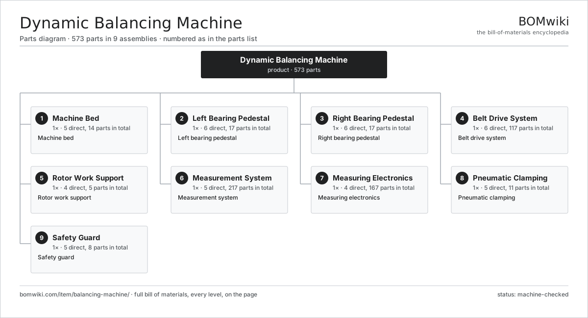
| # | Part | Qty | What it does |
|---|---|---|---|
| 1 | Machine Bed 5 parts | 1× | Machine bed |
| 2 | Left Bearing Pedestal 6 parts | 1× | Left bearing pedestal |
| 3 | Right Bearing Pedestal 6 parts | 1× | Right bearing pedestal |
| 4 | Belt Drive System 6 parts | 1× | Belt drive system |
| 5 | Rotor Work Support 4 parts | 1× | Rotor work support |
| 6 | Measurement System 5 parts | 1× | Measurement system |
| 7 | Measuring Electronics 4 parts | 1× | Measuring electronics |
| 8 | Pneumatic Clamping 5 parts | 1× | Pneumatic clamping |
| 9 | Safety Guard 5 parts | 1× | Safety guard |
3D model
No 3D model yet. Have a CAD file of this? Add a 3D model — STL renders right on this page; STEP, FreeCAD, and OpenSCAD sources are welcome too (openly licensed, like all 3D models on BOMwiki).
Build & assembly graph
expand / collapse · shared sub-assemblies converge · links to related products · est. labourTap an assembly to expand/collapse · tap a part to open it · use “Open page” for any node · drag to pan, scroll to zoom.
Bill of materials for Dynamic Balancing Machine
9 top-level lines · 96 rows shown · 573 parts total · indented to 3 levels| # | Item / sub-assembly | Part no. | Qty/assy | Ext. qty | Parts | Type |
|---|---|---|---|---|---|---|
| 1 | Machine Bed 5 parts | balancing-machine-bed | 1× | 1 | 14 | assembly |
| 1.1 | Cast Base | balancing-machine-base-casting | 1× | 1 | · | part |
| 1.2 | T-Slot Rail | balancing-machine-t-slot-rail | 2× | 2 | · | part |
| 1.3 | Leveling Foot | balancing-machine-leveling-foot | 6× | 6 | · | part |
| 1.4 | Pedestal Clamp | balancing-machine-pedestal-clamp | 4× | 4 | · | part |
| 1.5 | Fastener Set | fastener-set | 1× | 1 | · | part |
| 2 | Left Bearing Pedestal 6 parts | balancing-machine-pedestal-left | 1× | 1 | 17 | assembly |
| 2.1 | Pedestal Body | balancing-machine-pedestal-body | 1× | 1 | · | part |
| 2.2 | Roller Cradle 3 parts | balancing-machine-roller-cradle | 1× | 1 | 8 | assembly |
| 2.2.1 | Support Roller | balancing-machine-support-roller | 2× | 2 | · | part |
| 2.2.2 | Ball Bearing | ball-bearing | 4× | 4 | · | part |
| 2.2.3 | Roller Axle | balancing-machine-roller-axle | 2× | 2 | · | part |
| 2.3 | Vee-Block Insert | balancing-machine-vee-block | 1× | 1 | · | part |
| 2.4 | Leaf Suspension | balancing-machine-suspension-spring | 2× | 2 | · | part |
| 2.5 | Force/Vibration Pickup 4 parts | balancing-machine-force-pickup | 1× | 1 | 4 | assembly |
| 2.5.1 | Piezoelectric Element | piezo-element | 1× | 1 | · | part |
| 2.5.2 | Pickup Housing | balancing-machine-pickup-housing | 1× | 1 | · | part |
| 2.5.3 | Seismic Mass | balancing-machine-seismic-mass | 1× | 1 | · | part |
| 2.5.4 | Connector | connector | 1× | 1 | · | part |
| 2.6 | Measure/Lock Toggle | balancing-machine-pedestal-lock | 1× | 1 | · | part |
| 3 | Right Bearing Pedestal 6 parts | balancing-machine-pedestal-right | 1× | 1 | 17 | assembly |
| 3.1 | Pedestal Body | balancing-machine-pedestal-body | 1× | 1 | · | part |
| 3.2 | Roller Cradle 3 parts | balancing-machine-roller-cradle | 1× | 1 | 8 | assembly |
| 3.2.1 | Support Roller | balancing-machine-support-roller | 2× | 2 | · | part |
| 3.2.2 | Ball Bearing | ball-bearing | 4× | 4 | · | part |
| 3.2.3 | Roller Axle | balancing-machine-roller-axle | 2× | 2 | · | part |
| 3.3 | Vee-Block Insert | balancing-machine-vee-block | 1× | 1 | · | part |
| 3.4 | Leaf Suspension | balancing-machine-suspension-spring | 2× | 2 | · | part |
| 3.5 | Force/Vibration Pickup 4 parts | balancing-machine-force-pickup | 1× | 1 | 4 | assembly |
| 3.5.1 | Piezoelectric Element | piezo-element | 1× | 1 | · | part |
| 3.5.2 | Pickup Housing | balancing-machine-pickup-housing | 1× | 1 | · | part |
| 3.5.3 | Seismic Mass | balancing-machine-seismic-mass | 1× | 1 | · | part |
| 3.5.4 | Connector | connector | 1× | 1 | · | part |
| 3.6 | Measure/Lock Toggle | balancing-machine-pedestal-lock | 1× | 1 | · | part |
| 4 | Belt Drive System 6 parts | balancing-machine-drive | 1× | 1 | 117 | assembly |
| 4.1 | Drive Motor 4 parts | balancing-machine-drive-motor | 1× | 1 | 25 | assembly |
| 4.1.1 | Stator Assembly 3 parts + deeper › | stator-assembly | 1× | 1 | 3 | assembly |
| 4.1.2 | Rotor Assembly 4 parts + deeper › | rotor-assembly | 1× | 1 | 19 | assembly |
| 4.1.3 | Motor Housing | motor-housing | 1× | 1 | · | part |
| 4.1.4 | Ball Bearing | ball-bearing | 2× | 2 | · | part |
| 4.2 | Drive Spindle | balancing-machine-drive-spindle | 1× | 1 | · | part |
| 4.3 | Drive Belt | drive-belt | 1× | 1 | · | part |
| 4.4 | Belt Tensioner | balancing-machine-belt-tensioner | 1× | 1 | · | part |
| 4.5 | Variable-Frequency Drive 4 parts | balancing-machine-vfd | 1× | 1 | 88 | assembly |
| 4.5.1 | Bare PCB | pcb-bare | 1× | 1 | · | part |
| 4.5.2 | Power MOSFET | mosfet | 6× | 6 | · | part |
| 4.5.3 | Gate Driver IC | gate-driver-ic | 1× | 1 | · | part |
| 4.5.4 | SMD Passive (R/C/L) | smd-passives | 80× | 80 | · | part |
| 4.6 | End-Drive Coupling | balancing-machine-end-drive | 1× | 1 | · | part |
| 5 | Rotor Work Support 4 parts | balancing-machine-cradle | 1× | 1 | 5 | assembly |
| 5.1 | Balancing Arbor | balancing-machine-work-arbor | 1× | 1 | · | part |
| 5.2 | Axial Stop | balancing-machine-axial-stop | 1× | 1 | · | part |
| 5.3 | Index Collar | balancing-machine-index-collar | 1× | 1 | · | part |
| 5.4 | Cradle Counterweight | balancing-machine-counterweight | 2× | 2 | · | part |
| 6 | Measurement System 5 parts | balancing-machine-measurement | 1× | 1 | 217 | assembly |
| 6.1 | Phase Reference Photocell | balancing-machine-phase-photocell | 1× | 1 | · | part |
| 6.2 | Speed/Angle Encoder | balancing-machine-encoder | 1× | 1 | · | part |
| 6.3 | Charge Amplifier 3 parts | balancing-machine-charge-amp | 2× | 2 | 43 | assembly |
| 6.3.1 | Bare PCB | pcb-bare | 1× | 2 | · | part |
| 6.3.2 | SMD Passive (R/C/L) | smd-passives | 40× | 80 | · | part |
| 6.3.3 | Connector | connector | 2× | 4 | · | part |
| 6.4 | Signal Conditioning Board 5 parts | balancing-machine-signal-board | 1× | 1 | 128 | assembly |
| 6.4.1 | Bare PCB | pcb-bare | 1× | 1 | · | part |
| 6.4.2 | Microcontroller | mcu | 1× | 1 | · | part |
| 6.4.3 | Analog-to-Digital Converter | balancing-machine-adc | 2× | 2 | · | part |
| 6.4.4 | SMD Passive (R/C/L) | smd-passives | 120× | 120 | · | part |
| 6.4.5 | Connector | connector | 4× | 4 | · | part |
| 6.5 | Wire Bundle | wire-bundle | 1× | 1 | · | part |
| 7 | Measuring Electronics 4 parts | balancing-machine-electronics | 1× | 1 | 167 | assembly |
| 7.1 | Measuring Controller 4 parts | balancing-machine-controller | 1× | 1 | 161 | assembly |
| 7.1.1 | Bare PCB | pcb-bare | 1× | 1 | · | part |
| 7.1.2 | Microcontroller | mcu | 2× | 2 | · | part |
| 7.1.3 | SMD Passive (R/C/L) | smd-passives | 150× | 150 | · | part |
| 7.1.4 | Connector | connector | 8× | 8 | · | part |
| 7.2 | Operator HMI 4 parts | balancing-machine-hmi | 1× | 1 | 4 | assembly |
| 7.2.1 | LCD Panel | lcd-panel | 1× | 1 | · | part |
| 7.2.2 | Touch Digitizer | touch-digitizer | 1× | 1 | · | part |
| 7.2.3 | Bare PCB | pcb-bare | 1× | 1 | · | part |
| 7.2.4 | Microcontroller | mcu | 1× | 1 | · | part |
| 7.3 | Power Supply | power-supply | 1× | 1 | · | part |
| 7.4 | Electronics Cabinet | balancing-machine-cabinet | 1× | 1 | · | part |
| 8 | Pneumatic Clamping 5 parts | balancing-machine-pneumatic | 1× | 1 | 11 | assembly |
| 8.1 | Clamp Cylinder 3 parts | balancing-machine-clamp-cylinder | 2× | 2 | 3 | assembly |
| 8.1.1 | Cylinder Body | balancing-machine-cylinder-body | 1× | 2 | · | part |
| 8.1.2 | Piston Rod | balancing-machine-piston-rod | 1× | 2 | · | part |
| 8.1.3 | O-Ring Set | oring-set | 1× | 2 | · | part |
| 8.2 | Filter-Regulator Unit | balancing-machine-fr-unit | 1× | 1 | · | part |
| 8.3 | Solenoid Valve | balancing-machine-solenoid-valve | 2× | 2 | · | part |
| 8.4 | Pressure Sensor | pressure-sensor | 1× | 1 | · | part |
| 8.5 | Air Lines and Fittings | balancing-machine-air-line | 1× | 1 | · | part |
| 9 | Safety Guard 5 parts | balancing-machine-guard | 1× | 1 | 8 | assembly |
| 9.1 | Guard Frame | balancing-machine-guard-frame | 1× | 1 | · | part |
| 9.2 | Sheet Metal Panel | sheet-panel | 4× | 4 | · | part |
| 9.3 | Polycarbonate Window | window-polycarbonate | 1× | 1 | · | part |
| 9.4 | Guard Interlock | balancing-machine-guard-interlock | 1× | 1 | · | part |
| 9.5 | Emergency Stop | balancing-machine-estop | 1× | 1 | · | part |
Related products
same domain, ranked by shared parts Ultrasonic Welding Machine
269 parts · shares 10 with this page
Ultrasonic Welding Machine
269 parts · shares 10 with this page
 Industrial 3D Printer
218 parts · shares 17 with this page
Industrial 3D Printer
218 parts · shares 17 with this page
 Investment Casting Shell Line
869 parts · shares 20 with this page
Casting Fettling Machine
802 parts · shares 19 with this page
Investment Casting Shell Line
869 parts · shares 20 with this page
Casting Fettling Machine
802 parts · shares 19 with this page
 Injection Molding Machine
292 parts · shares 18 with this page
Industrial Planetary Mixer
176 parts · shares 17 with this page
Injection Molding Machine
292 parts · shares 18 with this page
Industrial Planetary Mixer
176 parts · shares 17 with this page
Sourcing: possible vendors
Prices, MOQ, and lead times are algorithmic estimates, not quotes, and not claims about these companies. Company mappings are curated by keyword; est. price band $5k–$2M. How estimates work| Vendor | HQ | Specialty | MOQ | Lead time |
|---|---|---|---|---|
| atlascopco.com ↗ | Stockholm, SE | Compressors & industrial | 10 units | 12–20 wks |
|
🇦🇹Andritz
andritz.com ↗
|
Graz, AT | Process plants & machinery | 10 units | 12–20 wks |
| buhlergroup.com ↗ | Uzwil, CH | Food & materials processing | 10 units | 12–20 wks |
| gea.com ↗ | Düsseldorf, DE | Process technology | 10 units | 12–20 wks |
| mhi.com ↗ | Tokyo, JP | Heavy machinery | 10 units | 12–20 wks |
1,080-word article