Metal Holding Furnace
ProductOverview
A metal holding furnace stores molten metal at a steady casting temperature so a die-casting or low-pressure machine can draw a precise shot whenever it needs one. It does not melt cold scrap; it receives metal that a melting furnace has already liquefied and keeps it ready. Its two jobs are holding the bath at a tight temperature, often within plus or minus 3 degrees Celsius, and dosing a repeatable quantity of clean metal on command. A holding and dosing furnace sits beside each casting cell, decoupling the casting rhythm from the central melt shop and removing the hand ladling that introduces oxide, temperature swing and dose-to-dose variation.
The furnace combines an insulated bath, a heat source, a metering delivery and a pressurisation circuit. The Holding Vessel stores the melt, the Heating System holds its temperature, the Dosing System delivers each shot, and the Pressurisation System supplies the gas pressure that lifts metal up the riser.
Holding the bath
The Holding Vessel is a steel Vessel Shell lined with a working Working Refractory in contact with the metal and a Backup Insulation backup layer that cuts standing heat loss to a few kilowatts per tonne. Two immersion Bath Thermocouple probes feed the temperature loop. Because the metal is sealed under the Furnace Lid with a Lid Seal around the rim, oxidation and dross formation drop sharply compared with an open bath, and the insulated enclosure keeps the heating duty low between casts. A Charge Well lets fresh metal top up the bath without breaking the seal over the dosing chamber.
Heating system
For aluminium and zinc, electric resistance heating is usual. Six or more Heating Element units, often silicon carbide rods, sit in the Radiant Roof above the bath, each carried in a ceramic Element Holder. An SCR Power Controller regulates power by phase angle so the elements deliver exactly the heat needed to balance standing loss plus the heat carried out in each shot. Electric heating gives clean, precise, low-emission temperature control and is the dominant choice where a tight casting window matters. Gas-fired variants use radiant burners under the bath where fuel cost or very high throughput favours combustion.
Dosing system
The defining feature of a dosing furnace is delivery of a known mass of metal per shot. The Pressurisation System applies a controlled inert gas pressure, set by a Proportional Valve and measured by a Pressure Sensor, to the sealed chamber above the bath. That pressure pushes metal up the refractory Riser Tube toward the heated Dosing Spout. A Stopper Rod, moved by a Servo Motor, opens the spout for a precisely timed interval to release the shot, then closes it. A Spout Heater keeps the spout above the metal freezing point so the tip never blocks between casts, and a Shot Sensor confirms each delivered volume. The combination of pressure dosing and stopper metering reaches roughly plus or minus 1 percent shot repeatability, which directly controls casting weight and scrap.
Pressurisation and safety
Nitrogen or argon from a Gas Regulator feeds the chamber, and the Proportional Valve trims pressure shot by shot to keep the dose constant as the bath level falls. A Pressure Relief Valve protects against overpressure and a fast Vent Valve dumps chamber pressure to reset cleanly between shots so the riser metal drops back and the next dose starts from a known datum. The inert atmosphere also blankets the bath, further suppressing oxidation of reactive alloys such as magnesium-bearing aluminium.
Control and integration
The Control Panel carries the Holding Furnace PLC, dual Temperature Controller loops and the dosing sequencer. It exchanges signals with the casting machine: the machine requests a shot, the furnace doses and reports completion, and temperature, pressure and shot data are logged for traceability. The Frame and Casing supports the vessel, carries the outer casing and includes a Tilt Cylinder so the bath can be drained for relining.
Applications
Holding furnaces serve high-pressure and low-pressure die casting, permanent mould casting and gravity casting, almost always for aluminium, magnesium and zinc alloys. Placed at the casting cell, a dosing furnace removes the ladle operator, stabilises pour temperature, cuts metal loss to dross, and feeds clean metal of repeatable weight to every shot. In automated die-casting lines several dosing furnaces run in parallel, each tied to one machine, fed in turn from a central melting or holding bath.
Maintenance and lining life
The working refractory is the main wearing item. As the lining erodes and absorbs metal the bath volume changes and the dosing calibration drifts, so the furnace is drained and relined on a planned campaign rather than run to failure. Element life is the next concern: silicon carbide rods age and rise in resistance, and the SCR controller compensates until a rod must be replaced. The stopper rod and dosing spout see the harshest duty because they cycle in and out of the metal on every shot, so they are treated as consumables and changed on schedule. Routine checks cover the lid seal, the inert gas supply pressure and the thermocouple calibration, since a drifting bath thermocouple quietly degrades casting quality before it triggers any alarm. Keeping the bath covered and the gas blanket intact between casts is the single biggest factor in low dross generation and long lining life.
Metal Holding Furnace parts and their functions
7 top-level parts · 90 parts in total · full bill of materials below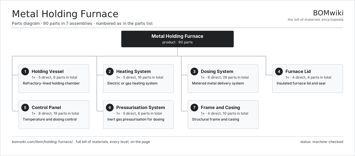
| # | Part | Qty | What it does |
|---|---|---|---|
| 1 | Holding Vessel 5 parts | 1× | Refractory-lined holding chamber |
| 2 | Heating System 5 parts | 1× | Electric or gas heating system |
| 3 | Dosing System 6 parts | 1× | Metered metal delivery system |
| 4 | Furnace Lid 4 parts | 1× | Insulated furnace lid and seal |
| 5 | Control Panel 8 parts | 1× | Temperature and dosing control |
| 6 | Pressurisation System 5 parts | 1× | Inert gas pressurisation for dosing |
| 7 | Frame and Casing 4 parts | 1× | Structural frame and casing |
3D model
No 3D model yet. Have a CAD file of this? Add a 3D model — STL renders right on this page; STEP, FreeCAD, and OpenSCAD sources are welcome too (openly licensed, like all 3D models on BOMwiki).
Build & assembly graph
expand / collapse · shared sub-assemblies converge · links to related products · est. labourTap an assembly to expand/collapse · tap a part to open it · use “Open page” for any node · drag to pan, scroll to zoom.
Bill of materials for Metal Holding Furnace
7 top-level lines · 48 rows shown · 90 parts total · indented to 3 levels| # | Item / sub-assembly | Part no. | Qty/assy | Ext. qty | Parts | Type |
|---|---|---|---|---|---|---|
| 1 | Holding Vessel 5 parts | holding-furnace-vessel | 1× | 1 | 6 | assembly |
| 1.1 | Vessel Shell | holding-furnace-shell | 1× | 1 | · | part |
| 1.2 | Working Refractory | holding-furnace-refractory | 1× | 1 | · | part |
| 1.3 | Backup Insulation | holding-furnace-insulation | 1× | 1 | · | part |
| 1.4 | Bath Thermocouple | holding-furnace-bath-thermocouple | 2× | 2 | · | part |
| 1.5 | Drain Block | holding-furnace-drain-block | 1× | 1 | · | part |
| 2 | Heating System 5 parts | holding-furnace-heating | 1× | 1 | 16 | assembly |
| 2.1 | Heating Element | heating-element | 6× | 6 | · | part |
| 2.2 | Element Holder | holding-furnace-element-holder | 6× | 6 | · | part |
| 2.3 | Power Contactor | holding-furnace-power-contactor | 2× | 2 | · | part |
| 2.4 | SCR Power Controller | holding-furnace-scr-controller | 1× | 1 | · | part |
| 2.5 | Radiant Roof | holding-furnace-radiant-roof | 1× | 1 | · | part |
| 3 | Dosing System 6 parts | holding-furnace-dosing | 1× | 1 | 29 | assembly |
| 3.1 | Riser Tube | holding-furnace-riser-tube | 1× | 1 | · | part |
| 3.2 | Dosing Spout | holding-furnace-dosing-spout | 1× | 1 | · | part |
| 3.3 | Stopper Rod | holding-furnace-stopper-rod | 1× | 1 | · | part |
| 3.4 | Servo Motor 4 parts | servo-motor | 1× | 1 | 24 | assembly |
| 3.4.1 | Stator Assembly 3 parts + deeper › | stator-assembly | 1× | 1 | 3 | assembly |
| 3.4.2 | Rotor Assembly 4 parts + deeper › | rotor-assembly | 1× | 1 | 19 | assembly |
| 3.4.3 | Encoder | encoder | 1× | 1 | · | part |
| 3.4.4 | Motor Housing | motor-housing | 1× | 1 | · | part |
| 3.5 | Spout Heater | holding-furnace-spout-heater | 1× | 1 | · | part |
| 3.6 | Shot Sensor | holding-furnace-shot-sensor | 1× | 1 | · | part |
| 4 | Furnace Lid 4 parts | holding-furnace-lid | 1× | 1 | 4 | assembly |
| 4.1 | Lid Shell | holding-furnace-lid-shell | 1× | 1 | · | part |
| 4.2 | Lid Seal | holding-furnace-lid-seal | 1× | 1 | · | part |
| 4.3 | Lid Lift Mechanism | holding-furnace-lid-lift | 1× | 1 | · | part |
| 4.4 | Charge Well | holding-furnace-charge-well | 1× | 1 | · | part |
| 5 | Control Panel 8 parts | holding-furnace-control-panel | 1× | 1 | 19 | assembly |
| 5.1 | Holding Furnace PLC | holding-furnace-plc | 1× | 1 | · | part |
| 5.2 | LCD Panel | lcd-panel | 1× | 1 | · | part |
| 5.3 | Temperature Controller | holding-furnace-temperature-controller | 2× | 2 | · | part |
| 5.4 | Relay | relay | 6× | 6 | · | part |
| 5.5 | Connector | connector | 6× | 6 | · | part |
| 5.6 | Wire Bundle | wire-bundle | 1× | 1 | · | part |
| 5.7 | Microcontroller | mcu | 1× | 1 | · | part |
| 5.8 | Bare PCB | pcb-bare | 1× | 1 | · | part |
| 6 | Pressurisation System 5 parts | holding-furnace-pressure-system | 1× | 1 | 6 | assembly |
| 6.1 | Gas Regulator | holding-furnace-gas-regulator | 1× | 1 | · | part |
| 6.2 | Proportional Valve | holding-furnace-proportional-valve | 1× | 1 | · | part |
| 6.3 | Pressure Sensor | pressure-sensor | 2× | 2 | · | part |
| 6.4 | Pressure Relief Valve | holding-furnace-relief-valve | 1× | 1 | · | part |
| 6.5 | Vent Valve | holding-furnace-vent-valve | 1× | 1 | · | part |
| 7 | Frame and Casing 4 parts | holding-furnace-frame | 1× | 1 | 10 | assembly |
| 7.1 | Base Frame | holding-furnace-base-frame | 1× | 1 | · | part |
| 7.2 | Sheet Metal Panel | sheet-panel | 4× | 4 | · | part |
| 7.3 | Tilt Cylinder | holding-furnace-tilt-cylinder | 1× | 1 | · | part |
| 7.4 | Furnace Castor | holding-furnace-castor | 4× | 4 | · | part |
Related products
same domain, ranked by shared parts Industrial Parts Washer
423 parts · shares 19 with this page
Industrial Parts Washer
423 parts · shares 19 with this page
 Industrial Ultrasonic Cleaner
787 parts · shares 19 with this page
Industrial Ultrasonic Cleaner
787 parts · shares 19 with this page
 Investment Casting Shell Line
869 parts · shares 19 with this page
Micro Injection Molding Machine
704 parts · shares 19 with this page
Investment Casting Shell Line
869 parts · shares 19 with this page
Micro Injection Molding Machine
704 parts · shares 19 with this page
Sourcing: possible vendors
Prices, MOQ, and lead times are algorithmic estimates, not quotes, and not claims about these companies. Company mappings are curated by keyword; est. price band $5k–$2M. How estimates work| Vendor | HQ | Specialty | MOQ | Lead time |
|---|---|---|---|---|
| atlascopco.com ↗ | Stockholm, SE | Compressors & industrial | 10 units | 12–20 wks |
|
🇦🇹Andritz
andritz.com ↗
|
Graz, AT | Process plants & machinery | 10 units | 12–20 wks |
| buhlergroup.com ↗ | Uzwil, CH | Food & materials processing | 10 units | 12–20 wks |
| gea.com ↗ | Düsseldorf, DE | Process technology | 10 units | 12–20 wks |
| mhi.com ↗ | Tokyo, JP | Heavy machinery | 10 units | 12–20 wks |
940-word article