Gravimetric Plastics Blender
ProductOverview
A gravimetric plastics blender meters two or more dry materials by weight and mixes them into a uniform batch that feeds an injection molding machine or extruder. Unlike a volumetric feeder that meters by screw revolutions or auger turns, a gravimetric unit weighs every component, so changes in pellet bulk density, pellet shape, or moisture do not shift the recipe. The blend can be base virgin resin plus regrind plus color masterbatch plus a functional additive, and the controller holds each fraction to within roughly one tenth of a percent of the target.
The machine sits above the feed throat of the molding press or on its own floor stand. Components arrive in supply hoppers, drop one at a time through dosing valves into a weigh bin that rests on load cells, and the weighed batch then falls into a mixing chamber before it reaches the press. Because the unit knows the actual weight consumed per batch, it can also report material usage, regrind ratio, and color cost per part, which is why gravimetric blending is standard on regulated and high-value molding lines.
Material handling and dosing
Each component has its own Resin Hopper style hopper sized to its share of the recipe. The base resin hopper is the largest, the Masterbatch Hopper and additive hoppers are small because color and additives are typically one to four percent of the blend. Every hopper carries a Level Sensor low-level probe and a sight glass so the operator can confirm supply.
Under each hopper is a dosing valve. The common design is a Slide Gate driven by a Gate Cylinder air cylinder, with a sized Gate Orifice that sets how fast pellets fall when the gate opens. The PLC opens one gate at a time and watches the weight climb. As the running weight approaches the target for that component, it can pulse the gate to dribble the last pellets in, which is how the unit reaches tight accuracy without overshoot. A Gate Position Switch reed switch confirms that each gate actually moved.
Weighing and mixing
The heart of the machine is the Weigh Bin Assembly. The weigh hopper hangs on three Load Cell strain gauge cells through flexure mounts that carry vertical load while rejecting side forces. The controller zeroes the empty bin, then records the incremental weight as each component is dropped in sequence. When all components for the batch are present, the Dump Valve flap opens and the batch falls into the mixing chamber. A draft shroud around the bin keeps air currents and machine vibration from corrupting the reading, which matters because the smallest additive doses can be a fraction of a gram.
Below the weigh bin the Mixing Chamber homogenizes the batch. A ribbon paddle on a driven shaft folds the components together so that color and additive are evenly distributed before the pellets reach the screw. The mixer runs only long enough to blend one batch, then discharges through a chute to the press throat. Mixing matters most for color: poor blending shows up as streaks or shade variation in the molded part.
Refilling and pneumatics
Supply hoppers are kept full by Vacuum Loader Set. Each loader is a cyclone receiver with a discharge flap and a cartridge filter; a central regenerative blower pulls pellets from a gaylord or silo through an antistatic hose into the receiver, and the flap drops them into the hopper when the vacuum stops. The blender meters and weighs while the loaders refill in the background, so the press never starves.
The dosing valves and the dump valve all run on compressed air. The Pneumatic System block conditions that air: a coalescing filter removes oil and water, a regulator sets working pressure, and a solenoid manifold switches each cylinder under PLC command. A pressure switch interlocks the system so that the unit will not try to dose if air pressure drops, which would give a false light batch.
Control and recipes
The Control System holds the recipe library, the dosing logic, and the weight calibration. A PLC sequences the gates, reads the Load-Cell Amplifier amplifier, and runs the mixer and loaders. The operator enters target percentages on the touchscreen, and the controller converts them to per-batch target weights. Self-correction is continuous: if one batch comes in slightly heavy on regrind, the next batch trims that gate. The unit logs throughput and consumption per material, which feeds cost reports and inventory.
Variants and materials
Blenders scale from small two-component throat units up to six-component central systems serving several presses. Hoppers, the weigh bin, and the mixer are stainless steel or coated aluminum so they resist abrasive glass-filled compounds. Conveying hoses are antistatic to stop fine dust from clinging. Higher accuracy versions use larger, lower-range load cells for small additive doses, and some add a separate micro-dosing feeder for liquid color.
Maintenance and failures
Routine care is the air filter, the load-cell calibration check with a known weight, and inspection of the slide-gate seals, which wear from abrasive fillers and cause leak-through that biases a dose. Loader filters clog with fines and must be cleaned so the receivers keep their vacuum. The most common faults are a sticking gate cylinder, a worn Gate Seal that lets pellets dribble between doses, and load-cell drift from a knock or from material packed against the draft shroud. Because every batch is weighed, a drifting cell shows up quickly as a recipe that no longer matches the molded part, which is the early warning the operator watches for.
Gravimetric Plastics Blender parts and their functions
8 top-level parts · 139 parts in total · full bill of materials below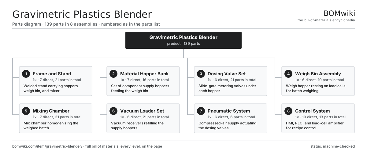
| # | Part | Qty | What it does |
|---|---|---|---|
| 1 | Frame and Stand 7 parts | 1× | Welded stand carrying hoppers, weigh bin, and mixer |
| 2 | Material Hopper Bank 7 parts | 1× | Set of component supply hoppers feeding the weigh bin |
| 3 | Dosing Valve Set 6 parts | 1× | Slide-gate metering valves under each hopper |
| 4 | Weigh Bin Assembly 6 parts | 1× | Weigh hopper resting on load cells for batch weighing |
| 5 | Mixing Chamber 7 parts | 1× | Mix chamber homogenizing the weighed batch |
| 6 | Vacuum Loader Set 6 parts | 1× | Vacuum receivers refilling the supply hoppers |
| 7 | Pneumatic System 6 parts | 1× | Compressed-air supply actuating the dosing valves |
| 8 | Control System 10 parts | 1× | HMI, PLC, and load-cell amplifier for recipe control |
3D model
No 3D model yet. Have a CAD file of this? Add a 3D model — STL renders right on this page; STEP, FreeCAD, and OpenSCAD sources are welcome too (openly licensed, like all 3D models on BOMwiki).
Build & assembly graph
expand / collapse · shared sub-assemblies converge · links to related products · est. labourTap an assembly to expand/collapse · tap a part to open it · use “Open page” for any node · drag to pan, scroll to zoom.
Bill of materials for Gravimetric Plastics Blender
8 top-level lines · 67 rows shown · 139 parts total · indented to 3 levels| # | Item / sub-assembly | Part no. | Qty/assy | Ext. qty | Parts | Type |
|---|---|---|---|---|---|---|
| 1 | Frame and Stand 7 parts | gravimetric-blender-frame | 1× | 1 | 21 | assembly |
| 1.1 | Frame Uprights | gravimetric-blender-frame-uprights | 4× | 4 | · | part |
| 1.2 | Frame Cross Rails | gravimetric-blender-frame-cross-rails | 6× | 6 | · | part |
| 1.3 | Hopper Deck | gravimetric-blender-frame-hopper-deck | 1× | 1 | · | part |
| 1.4 | Mounting Feet | gravimetric-blender-frame-mount-feet | 4× | 4 | · | part |
| 1.5 | Throat Adapter | gravimetric-blender-frame-throat-adapter | 1× | 1 | · | part |
| 1.6 | Sheet Metal Panel | sheet-panel | 4× | 4 | · | part |
| 1.7 | Fastener Set | fastener-set | 1× | 1 | · | part |
| 2 | Material Hopper Bank 7 parts | gravimetric-blender-material-hoppers | 1× | 1 | 16 | assembly |
| 2.1 | Resin Hopper | gravimetric-blender-resin-hopper | 1× | 1 | · | part |
| 2.2 | Regrind Hopper | gravimetric-blender-regrind-hopper | 1× | 1 | · | part |
| 2.3 | Masterbatch Hopper | gravimetric-blender-masterbatch-hopper | 1× | 1 | · | part |
| 2.4 | Additive Hopper | gravimetric-blender-additive-hopper | 1× | 1 | · | part |
| 2.5 | Hopper Lid | gravimetric-blender-hopper-lid | 4× | 4 | · | part |
| 2.6 | Level Sensor | gravimetric-blender-level-sensor | 4× | 4 | · | part |
| 2.7 | Sight Glass | gravimetric-blender-sight-glass | 4× | 4 | · | part |
| 3 | Dosing Valve Set 6 parts | gravimetric-blender-dosing-valves | 1× | 1 | 21 | assembly |
| 3.1 | Slide Gate | gravimetric-blender-slide-gate | 4× | 4 | · | part |
| 3.2 | Gate Cylinder | gravimetric-blender-gate-cylinder | 4× | 4 | · | part |
| 3.3 | Gate Orifice | gravimetric-blender-gate-orifice | 4× | 4 | · | part |
| 3.4 | Gate Seal | gravimetric-blender-gate-seal | 4× | 4 | · | part |
| 3.5 | Gate Position Switch | gravimetric-blender-position-switch | 4× | 4 | · | part |
| 3.6 | O-Ring Set | oring-set | 1× | 1 | · | part |
| 4 | Weigh Bin Assembly 6 parts | gravimetric-blender-weigh-bin | 1× | 1 | 10 | assembly |
| 4.1 | Weigh Hopper | gravimetric-blender-weigh-hopper | 1× | 1 | · | part |
| 4.2 | Load Cell | gravimetric-blender-load-cell | 3× | 3 | · | part |
| 4.3 | Dump Valve | gravimetric-blender-dump-valve | 1× | 1 | · | part |
| 4.4 | Dump Cylinder | gravimetric-blender-dump-cylinder | 1× | 1 | · | part |
| 4.5 | Weigh Mount | gravimetric-blender-weigh-mount | 3× | 3 | · | part |
| 4.6 | Draft Shroud | gravimetric-blender-shroud | 1× | 1 | · | part |
| 5 | Mixing Chamber 7 parts | gravimetric-blender-mixing-chamber | 1× | 1 | 31 | assembly |
| 5.1 | Mix Chamber Body | gravimetric-blender-mix-chamber-body | 1× | 1 | · | part |
| 5.2 | Mix Paddle | gravimetric-blender-mix-paddle | 1× | 1 | · | part |
| 5.3 | Mix Shaft | gravimetric-blender-mix-shaft | 1× | 1 | · | part |
| 5.4 | Servo Motor 4 parts | servo-motor | 1× | 1 | 24 | assembly |
| 5.4.1 | Stator Assembly 3 parts + deeper › | stator-assembly | 1× | 1 | 3 | assembly |
| 5.4.2 | Rotor Assembly 4 parts + deeper › | rotor-assembly | 1× | 1 | 19 | assembly |
| 5.4.3 | Encoder | encoder | 1× | 1 | · | part |
| 5.4.4 | Motor Housing | motor-housing | 1× | 1 | · | part |
| 5.5 | Ball Bearing | ball-bearing | 2× | 2 | · | part |
| 5.6 | Oil Seal | oil-seal | 1× | 1 | · | part |
| 5.7 | Discharge Chute | gravimetric-blender-discharge-chute | 1× | 1 | · | part |
| 6 | Vacuum Loader Set 6 parts | gravimetric-blender-vacuum-loaders | 1× | 1 | 21 | assembly |
| 6.1 | Loader Receiver | gravimetric-blender-loader-receiver | 4× | 4 | · | part |
| 6.2 | Loader Flap | gravimetric-blender-loader-flap | 4× | 4 | · | part |
| 6.3 | Loader Filter | gravimetric-blender-loader-filter | 4× | 4 | · | part |
| 6.4 | Vacuum Blower | gravimetric-blender-vacuum-pump | 1× | 1 | · | part |
| 6.5 | Pickup Wand | gravimetric-blender-pickup-wand | 4× | 4 | · | part |
| 6.6 | Conveying Hose | gravimetric-blender-conveying-hose | 4× | 4 | · | part |
| 7 | Pneumatic System 6 parts | gravimetric-blender-pneumatics | 1× | 1 | 6 | assembly |
| 7.1 | Air Regulator | gravimetric-blender-air-regulator | 1× | 1 | · | part |
| 7.2 | Air Filter | gravimetric-blender-air-filter | 1× | 1 | · | part |
| 7.3 | Solenoid Bank | gravimetric-blender-solenoid-bank | 1× | 1 | · | part |
| 7.4 | Air Reservoir | gravimetric-blender-air-reservoir | 1× | 1 | · | part |
| 7.5 | Air Pressure Switch | gravimetric-blender-pressure-switch | 1× | 1 | · | part |
| 7.6 | Pressure Sensor | pressure-sensor | 1× | 1 | · | part |
| 8 | Control System 10 parts | gravimetric-blender-controller | 1× | 1 | 13 | assembly |
| 8.1 | PLC | gravimetric-blender-plc | 1× | 1 | · | part |
| 8.2 | Load-Cell Amplifier | gravimetric-blender-load-cell-amp | 1× | 1 | · | part |
| 8.3 | LCD Panel | lcd-panel | 1× | 1 | · | part |
| 8.4 | Power Supply | power-supply | 1× | 1 | · | part |
| 8.5 | Bare PCB | pcb-bare | 1× | 1 | · | part |
| 8.6 | Microcontroller | mcu | 1× | 1 | · | part |
| 8.7 | SMD Passive (R/C/L) | smd-passives | 1× | 1 | · | part |
| 8.8 | Relay | relay | 4× | 4 | · | part |
| 8.9 | Connector | connector | 1× | 1 | · | part |
| 8.10 | Wire Bundle | wire-bundle | 1× | 1 | · | part |
Related products
same domain, ranked by shared parts Industrial Parts Washer
423 parts · shares 22 with this page
Vertical Injection Molding Machine
264 parts · shares 22 with this page
Industrial Parts Washer
423 parts · shares 22 with this page
Vertical Injection Molding Machine
264 parts · shares 22 with this page
 Foundry Sand Mixer
93 parts · shares 21 with this page
Coil Coating Line
1,767 parts · shares 21 with this page
Foundry Sand Mixer
93 parts · shares 21 with this page
Coil Coating Line
1,767 parts · shares 21 with this page
 Rubber Extrusion Line
524 parts · shares 21 with this page
Rubber Extrusion Line
524 parts · shares 21 with this page
Sourcing: possible vendors
Prices, MOQ, and lead times are algorithmic estimates, not quotes, and not claims about these companies. Company mappings are curated by keyword; est. price band $5k–$2M. How estimates work| Vendor | HQ | Specialty | MOQ | Lead time |
|---|---|---|---|---|
| atlascopco.com ↗ | Stockholm, SE | Compressors & industrial | 10 units | 12–20 wks |
|
🇦🇹Andritz
andritz.com ↗
|
Graz, AT | Process plants & machinery | 10 units | 12–20 wks |
| buhlergroup.com ↗ | Uzwil, CH | Food & materials processing | 10 units | 12–20 wks |
| gea.com ↗ | Düsseldorf, DE | Process technology | 10 units | 12–20 wks |
| mhi.com ↗ | Tokyo, JP | Heavy machinery | 10 units | 12–20 wks |
963-word article