Rubber Calender
ProductOverview
A rubber calender forms warm rubber compound into a continuous sheet of controlled thickness, or laminates that compound onto fabric and cord. It is a precision machine despite its mass: rolls weighing several tonnes set a gap to a hundredth of a millimetre and hold it across a web up to 2.5 metres wide. Calenders sit downstream of an internal mixer and warm-up mills, taking soft stock and turning it into the sheet stock used for tyre plies, conveyor belts, hose, roofing membrane, and rubberised fabric.
The machine carries three or four heavy chilled-iron rolls in a stack. Common layouts are the inverted-L, the S or Z, and the four-roll arrangement that gives two independent nips. Rolls are heated or cooled, driven at controllable speed ratios, and pressed apart by enormous separating force that the frame and nip system must resist without losing gauge.
How it works
Warm compound arrives on the Feed Conveyor from a warm-up mill, sometimes sized first by a Strip Cutter. It is laid into the top nip of the Roll Stack, where it forms a rolling bank held to width by the Stock Side Guide. As the rolls turn, the bank is dragged through the nip and squeezed to a thin film on the roll surface.
The gap, and therefore the sheet thickness, is set by the Nip Adjustment Screw driven by the Screw-Down Gear Motor under each Bearing Chock. Separating force at the nip tries to spread the rolls and bow them in the middle, which would make the sheet thicker at the centre. The machine fights this two ways: the Roll Bending Cylinder applies bending moments to the roll necks, and the Roll Crossing Mechanism skews one roll axis slightly. A Nip Load Cell reads the actual separating force for overload protection and gauge correction.
When the calender coats fabric, cloth is fed into a nip alongside the compound so the rubber is pressed into the weave. A friction calender runs adjacent rolls at different surface speeds, set by the Friction Ratio Gear, so the faster roll wipes rubber into the fabric. After the last nip, the sheet passes the Doctor Blade and goes to the take-off section.
Rolls and frame
Each Calender Roll is chilled cast iron with a hard wear skin over a tougher core, ground true and slightly crowned to offset bending. The rolls turn on heavy Roll Neck Bearing units carried in the Bearing Chock inside the housing windows. Peripheral Roll Drilling drilling carries heating or cooling media close to the surface for even temperature, fed through a Roll Rotary Joint at the roll end.
The Frame and Housings takes the separating load. Two cast steel Side Housing members stand on a Bedplate, tied by Tie Rod members and stiffened by a Cross Beam pair. Frame rigidity is what lets the screw-down and bending systems hold gauge; any frame stretch shows up directly as thickness error.
Drive and temperature control
The Main Drive Motor feeds a reduction gear in the Gearbox Housing, then a Pinion Stand splits torque to each roll. A Universal Drive Spindle couples each pinion to its roll neck so the roll can move on its screw-down without losing drive. Roll temperature comes from the Roll Temperature Control system: a Roll Temperature Unit blends steam from the Steam Control Valve and water from the Water Control Valve, with a Roll Thermocouple closing the loop and a Condensate Trap returning steam condensate. Temperature sets compound tack and flow, so it is held tightly per roll.
Take-off, gauge, and wind-up
After the stack, the Take-Off Roll draws the sheet onto a bank of water-cooled Cooling Drum units, sometimes through a Cooling Festoon for extra cooling dwell, with a Dancer Roll holding line tension. A Thickness Gauge traverses the web on its Gauge O-Frame, and the Profile Controller feeds corrections back to the bending and crossing systems so the cross-web profile stays flat. The Edge Trim Knife knives clean the edges and a Trim Take-Up collects the scrap. Finished sheet is rolled on the Wind-Up Mandrel with interleaved liner cloth paid out by the Liner Unwind so the tacky sheet does not block.
Materials and applications
Compounds include natural rubber, SBR, EPDM, butyl, and nitrile, with carbon black or silica reinforcement. Calenders make tyre inner liner and ply skim, conveyor belt covers, hose sheet, single-ply roofing, and rubberised textiles for diaphragms and protective wear. Sheet gauge tolerance on a well-set machine reaches ±0.01 mm.
Safety, maintenance, and failures
Calender nips are among the most dangerous points in a rubber plant. Each roll carries a Nip Trip Bar across the in-running nip that crash-stops the line through the Safety Relay and Fast-Stop Brake, backed by guards and an Emergency Stop Station network. Maintenance centres on the Calender Roll surface, which is reground when crown or finish degrades, and the Roll Neck Bearing units, which are tracked by the Lubrication System system through its Lube Oil Cooler and Lube Oil Filter. Common faults are gauge drift from a worn Nip Adjustment Screw, temperature streaks from a fouled Roll Rotary Joint or scaled drilling, and sheet defects from a nicked Doctor Blade or uneven bank.
Rubber Calender parts and their functions
11 top-level parts · 174 parts in total · full bill of materials below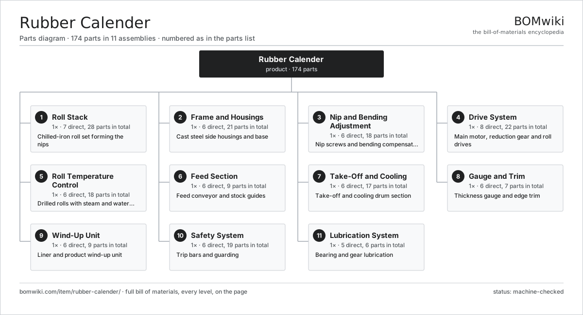
| # | Part | Qty | What it does |
|---|---|---|---|
| 1 | Roll Stack 7 parts | 1× | Chilled-iron roll set forming the nips |
| 2 | Frame and Housings 6 parts | 1× | Cast steel side housings and base |
| 3 | Nip and Bending Adjustment 6 parts | 1× | Nip screws and bending compensation |
| 4 | Drive System 8 parts | 1× | Main motor, reduction gear and roll drives |
| 5 | Roll Temperature Control 6 parts | 1× | Drilled rolls with steam and water joints |
| 6 | Feed Section 6 parts | 1× | Feed conveyor and stock guides |
| 7 | Take-Off and Cooling 6 parts | 1× | Take-off and cooling drum section |
| 8 | Gauge and Trim 6 parts | 1× | Thickness gauge and edge trim |
| 9 | Wind-Up Unit 6 parts | 1× | Liner and product wind-up unit |
| 10 | Safety System 6 parts | 1× | Trip bars and guarding |
| 11 | Lubrication System 5 parts | 1× | Bearing and gear lubrication |
3D model
No 3D model yet. Have a CAD file of this? Add a 3D model — STL renders right on this page; STEP, FreeCAD, and OpenSCAD sources are welcome too (openly licensed, like all 3D models on BOMwiki).
Build & assembly graph
expand / collapse · shared sub-assemblies converge · links to related products · est. labourTap an assembly to expand/collapse · tap a part to open it · use “Open page” for any node · drag to pan, scroll to zoom.
Bill of materials for Rubber Calender
11 top-level lines · 79 rows shown · 174 parts total · indented to 3 levels| # | Item / sub-assembly | Part no. | Qty/assy | Ext. qty | Parts | Type |
|---|---|---|---|---|---|---|
| 1 | Roll Stack 7 parts | rubber-calender-roll-stack | 1× | 1 | 28 | assembly |
| 1.1 | Calender Roll | rubber-calender-roll | 4× | 4 | · | part |
| 1.2 | Roll Neck Bearing | rubber-calender-roll-bearing | 8× | 8 | · | part |
| 1.3 | Roll Journal | rubber-calender-roll-journal | 4× | 4 | · | part |
| 1.4 | Roll Drilling | rubber-calender-roll-jacket | 4× | 4 | · | part |
| 1.5 | Doctor Blade | rubber-calender-doctor-blade | 2× | 2 | · | part |
| 1.6 | Stock Side Guide | rubber-calender-stock-guide | 2× | 2 | · | part |
| 1.7 | Roll Rotary Joint | rubber-calender-rotary-joint | 4× | 4 | · | part |
| 2 | Frame and Housings 6 parts | rubber-calender-frame | 1× | 1 | 21 | assembly |
| 2.1 | Side Housing | rubber-calender-side-housing | 2× | 2 | · | part |
| 2.2 | Bedplate | rubber-calender-bedplate | 1× | 1 | · | part |
| 2.3 | Tie Rod | rubber-calender-tie-rod | 4× | 4 | · | part |
| 2.4 | Bearing Chock | rubber-calender-bearing-chock | 8× | 8 | · | part |
| 2.5 | Cross Beam | rubber-calender-cross-beam | 2× | 2 | · | part |
| 2.6 | Fastener Set | fastener-set | 4× | 4 | · | part |
| 3 | Nip and Bending Adjustment 6 parts | rubber-calender-nip-adjust | 1× | 1 | 18 | assembly |
| 3.1 | Nip Adjustment Screw | rubber-calender-nip-screw | 4× | 4 | · | part |
| 3.2 | Screw-Down Gear Motor | rubber-calender-nip-motor | 2× | 2 | · | part |
| 3.3 | Roll Bending Cylinder | rubber-calender-bending-cyl | 4× | 4 | · | part |
| 3.4 | Roll Crossing Mechanism | rubber-calender-crossing-mech | 2× | 2 | · | part |
| 3.5 | Nip Load Cell | rubber-calender-load-cell | 4× | 4 | · | part |
| 3.6 | Roll Gap Sensor | rubber-calender-gap-sensor | 2× | 2 | · | part |
| 4 | Drive System 8 parts | rubber-calender-drive | 1× | 1 | 22 | assembly |
| 4.1 | Main Drive Motor | rubber-calender-main-motor | 1× | 1 | · | part |
| 4.2 | Gearbox Housing | gearbox-housing | 1× | 1 | · | part |
| 4.3 | Helical Gear Pair | gear-pair | 3× | 3 | · | part |
| 4.4 | Pinion Stand | rubber-calender-pinion-stand | 1× | 1 | · | part |
| 4.5 | Universal Drive Spindle | rubber-calender-universal-shaft | 4× | 4 | · | part |
| 4.6 | Friction Ratio Gear | rubber-calender-friction-gear | 2× | 2 | · | part |
| 4.7 | Ball Bearing | ball-bearing | 6× | 6 | · | part |
| 4.8 | Oil Seal | oil-seal | 4× | 4 | · | part |
| 5 | Roll Temperature Control 6 parts | rubber-calender-temp-control | 1× | 1 | 18 | assembly |
| 5.1 | Roll Temperature Unit | rubber-calender-tcu | 1× | 1 | · | part |
| 5.2 | Steam Control Valve | rubber-calender-steam-valve | 4× | 4 | · | part |
| 5.3 | Water Control Valve | rubber-calender-water-valve | 4× | 4 | · | part |
| 5.4 | Roll Thermocouple | rubber-calender-roll-thermocouple | 4× | 4 | · | part |
| 5.5 | Condensate Trap | rubber-calender-condensate-trap | 4× | 4 | · | part |
| 5.6 | Media Manifold | rubber-calender-temp-manifold | 1× | 1 | · | part |
| 6 | Feed Section 6 parts | rubber-calender-feed | 1× | 1 | 9 | assembly |
| 6.1 | Feed Conveyor | rubber-calender-feed-conveyor | 1× | 1 | · | part |
| 6.2 | Feed Conveyor Belt | rubber-calender-feed-belt | 1× | 1 | · | part |
| 6.3 | Conveyor Roller | rubber-calender-feed-roller | 4× | 4 | · | part |
| 6.4 | Feed Drive Motor | rubber-calender-feed-motor | 1× | 1 | · | part |
| 6.5 | Strip Cutter | rubber-calender-strip-cutter | 1× | 1 | · | part |
| 6.6 | Drive Belt | drive-belt | 1× | 1 | · | part |
| 7 | Take-Off and Cooling 6 parts | rubber-calender-takeoff | 1× | 1 | 17 | assembly |
| 7.1 | Take-Off Roll | rubber-calender-takeoff-roll | 2× | 2 | · | part |
| 7.2 | Cooling Drum | rubber-calender-cooling-drum | 4× | 4 | · | part |
| 7.3 | Cooling Festoon | rubber-calender-festoon | 1× | 1 | · | part |
| 7.4 | Take-Off Motor | rubber-calender-takeoff-motor | 1× | 1 | · | part |
| 7.5 | Dancer Roll | rubber-calender-dancer | 1× | 1 | · | part |
| 7.6 | Ball Bearing | ball-bearing | 8× | 8 | · | part |
| 8 | Gauge and Trim 6 parts | rubber-calender-gauge | 1× | 1 | 7 | assembly |
| 8.1 | Thickness Gauge | rubber-calender-beta-gauge | 1× | 1 | · | part |
| 8.2 | Gauge O-Frame | rubber-calender-gauge-frame | 1× | 1 | · | part |
| 8.3 | Edge Trim Knife | rubber-calender-edge-trim | 2× | 2 | · | part |
| 8.4 | Trim Take-Up | rubber-calender-trim-winder | 1× | 1 | · | part |
| 8.5 | Profile Controller | rubber-calender-profile-controller | 1× | 1 | · | part |
| 8.6 | Connector | connector | 1× | 1 | · | part |
| 9 | Wind-Up Unit 6 parts | rubber-calender-windup | 1× | 1 | 9 | assembly |
| 9.1 | Wind-Up Mandrel | rubber-calender-windup-shaft | 1× | 1 | · | part |
| 9.2 | Liner Unwind | rubber-calender-liner-unwind | 1× | 1 | · | part |
| 9.3 | Wind-Up Motor | rubber-calender-windup-motor | 1× | 1 | · | part |
| 9.4 | Liner Tension Brake | rubber-calender-windup-tension | 1× | 1 | · | part |
| 9.5 | Wind-Up Frame | rubber-calender-windup-frame | 1× | 1 | · | part |
| 9.6 | Ball Bearing | ball-bearing | 4× | 4 | · | part |
| 10 | Safety System 6 parts | rubber-calender-safety | 1× | 1 | 19 | assembly |
| 10.1 | Nip Trip Bar | rubber-calender-trip-bar | 4× | 4 | · | part |
| 10.2 | Nip Guard | rubber-calender-guard | 4× | 4 | · | part |
| 10.3 | Emergency Stop Station | rubber-calender-estop | 4× | 4 | · | part |
| 10.4 | Safety Relay | rubber-calender-safety-relay | 1× | 1 | · | part |
| 10.5 | Fast-Stop Brake | rubber-calender-brake | 2× | 2 | · | part |
| 10.6 | Relay | relay | 4× | 4 | · | part |
| 11 | Lubrication System 5 parts | rubber-calender-lube | 1× | 1 | 6 | assembly |
| 11.1 | Lube Oil Pump | rubber-calender-lube-pump | 1× | 1 | · | part |
| 11.2 | Lube Oil Cooler | rubber-calender-lube-cooler | 1× | 1 | · | part |
| 11.3 | Lube Oil Filter | rubber-calender-lube-filter | 1× | 1 | · | part |
| 11.4 | Lube Distribution Line | rubber-calender-lube-line | 1× | 1 | · | part |
| 11.5 | Lube Monitor | rubber-calender-lube-sensor | 2× | 2 | · | part |
Related products
same domain, ranked by shared parts Decanter Centrifuge
172 parts · shares 6 with this page
Decanter Centrifuge
172 parts · shares 6 with this page
 Foundry Sand Mixer
93 parts · shares 6 with this page
Hammer Mill
790 parts · shares 6 with this page
Foundry Sand Mixer
93 parts · shares 6 with this page
Hammer Mill
790 parts · shares 6 with this page
 Industrial Parts Washer
423 parts · shares 6 with this page
Industrial Planetary Mixer
176 parts · shares 6 with this page
Industrial Parts Washer
423 parts · shares 6 with this page
Industrial Planetary Mixer
176 parts · shares 6 with this page
Sourcing: possible vendors
Prices, MOQ, and lead times are algorithmic estimates, not quotes, and not claims about these companies. Company mappings are curated by keyword; est. price band $5k–$2M. How estimates work| Vendor | HQ | Specialty | MOQ | Lead time |
|---|---|---|---|---|
| atlascopco.com ↗ | Stockholm, SE | Compressors & industrial | 10 units | 12–20 wks |
|
🇦🇹Andritz
andritz.com ↗
|
Graz, AT | Process plants & machinery | 10 units | 12–20 wks |
| buhlergroup.com ↗ | Uzwil, CH | Food & materials processing | 10 units | 12–20 wks |
| gea.com ↗ | Düsseldorf, DE | Process technology | 10 units | 12–20 wks |
| mhi.com ↗ | Tokyo, JP | Heavy machinery | 10 units | 12–20 wks |
957-word article