Induction Melting Furnace
ProductOverview
A coreless induction melting furnace melts metal by electromagnetic induction rather than by burning fuel against the charge. A medium-frequency alternating current flows through a water-cooled copper coil wound around a refractory-lined crucible. The coil sets up an alternating magnetic field that passes through the crucible wall and induces circulating eddy currents in the metal inside. Those eddy currents heat the metal by its own electrical resistance, so the heat is generated within the charge itself. The same field stirs the molten bath, which gives a uniform composition and temperature without any mechanical agitation. Foundries use these furnaces to melt cast iron, carbon and alloy steel, copper, brass, aluminium and precious metals.
The furnace is built around a small number of high-stress subsystems. The Crucible and Refractory Lining holds the charge and isolates it from the live coil. The Induction Coil Assembly both carries the working current and cools itself. The Medium-Frequency Power Supply turns mains power into the medium-frequency current the coil needs, and the Capacitor Bank tunes the circuit to resonance so the supply only has to make up real losses.
How induction melting works
Mains power, typically three-phase at 400 V to 11 kV, enters the Isolation Transformer and then the Thyristor Rectifier, which produces a smoothed DC link. The Medium-Frequency Inverter chops that DC into an alternating current at the chosen working frequency, between 250 Hz for large furnaces and 10 kHz for small crucible units. Smaller charges need higher frequency because the depth that current penetrates into the metal, the skin depth, must stay smaller than the piece being melted for the induction to couple efficiently.
The coil and capacitors form a resonant tank circuit. At resonance the large reactive current circulates between coil and capacitors, and the converter only supplies the real power lost as heat in the charge and the coil. The Power Regulator continuously trims frequency and power to hold resonance as the charge changes from cold solid scrap to a fully molten bath, because the electrical properties of the load shift dramatically through the melt.
Crucible and refractory lining
The crucible is the consumable heart of the furnace. A welded Crucible Steel Shell carries an insulating Coil Grout Layer layer and then the working Refractory Lining. The lining is rammed in place as a dry granular refractory around a sacrificial steel Lining Former, then sintered hard by melting the first heat against it. Silica linings suit grey iron, alumina and magnesia suit steel and ductile iron. An Lining Leak Electrode electrode grid sits between lining and coil; if metal penetrates a worn lining the grid earths and trips the furnace before molten metal reaches the live coil. Lining life ranges from 50 heats for steel to several hundred for iron.
Coil and cooling
The Hollow Copper Conductor is hollow so cooling water can flow through the same copper that carries the current. Interturn Coil Interturn Insulation withstands the coil voltage and the radiant heat from the crucible. Laminated Magnetic Yoke bars around the outside return the magnetic flux and clamp the coil stack so it cannot move under the strong magnetic forces. The Cooling Water System runs a closed loop of deionised water, kept below 10 microsiemens per centimetre by a Deioniser Cartridge so it does not conduct between coil turns. A plate Plate Heat Exchanger passes that heat to a secondary loop and a cooling tower. Loss of cooling flow, sensed by a Cooling Flow Switch, instantly cuts power, because the coil would melt within seconds without water.
Tilting and pouring
When the melt is ready the whole furnace body tilts forward to pour. The Tilting Frame and Furnace Body pivots on two Trunnion Shaft shafts running in heavy bearings. Two Tilt Cylinder units, fed by the Hydraulic Power Pack, swing the furnace through up to 95 degrees so the Pouring Spout empties the bath into a ladle. A gas Hydraulic Accumulator holds the furnace at angle if power is lost mid-pour, so a full crucible never crashes back uncontrolled.
Control and safety
The Control and Instrumentation Panel carries the Furnace PLC, the operator touchscreen and the regulation electronics. An optical Optical Pyrometer reads bath temperature without contact. Interlocks chain together cooling flow, water conductivity, panel doors and the Emergency Stop buttons so that any fault drops the converter. At shutdown the Discharge Resistor safely bleeds the capacitor bank, which otherwise holds a lethal charge.
Operation and applications
Operators charge cold scrap, often topping up as the bath sinks, and the magnetic stirring blends alloy additions evenly. Power is run flat out for fast melting, then backed off to a holding level once temperature is reached. Because heat comes from inside the metal and not from a flame, melt loss and oxidation are low, alloying is precise, and the workplace stays cooler and cleaner than with a cupola or fuel-fired furnace. These furnaces serve job foundries, automotive casting plants, steel mini-mills and recycling operations, where fast batch melting and tight metallurgical control matter more than the lowest possible energy cost.
Induction Melting Furnace parts and their functions
8 top-level parts · 110 parts in total · full bill of materials below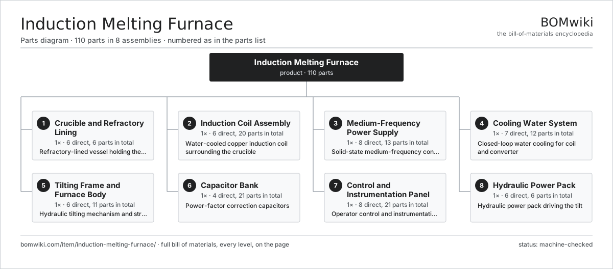
| # | Part | Qty | What it does |
|---|---|---|---|
| 1 | Crucible and Refractory Lining 6 parts | 1× | Refractory-lined vessel holding the metal charge |
| 2 | Induction Coil Assembly 6 parts | 1× | Water-cooled copper induction coil surrounding the crucible |
| 3 | Medium-Frequency Power Supply 8 parts | 1× | Solid-state medium-frequency converter |
| 4 | Cooling Water System 7 parts | 1× | Closed-loop water cooling for coil and converter |
| 5 | Tilting Frame and Furnace Body 6 parts | 1× | Hydraulic tilting mechanism and structural frame |
| 6 | Capacitor Bank 4 parts | 1× | Power-factor correction capacitors |
| 7 | Control and Instrumentation Panel 8 parts | 1× | Operator control and instrumentation panel |
| 8 | Hydraulic Power Pack 6 parts | 1× | Hydraulic power pack driving the tilt |
3D model
No 3D model yet. Have a CAD file of this? Add a 3D model — STL renders right on this page; STEP, FreeCAD, and OpenSCAD sources are welcome too (openly licensed, like all 3D models on BOMwiki).
Build & assembly graph
expand / collapse · shared sub-assemblies converge · links to related products · est. labourTap an assembly to expand/collapse · tap a part to open it · use “Open page” for any node · drag to pan, scroll to zoom.
Bill of materials for Induction Melting Furnace
8 top-level lines · 59 rows shown · 110 parts total · indented to 3 levels| # | Item / sub-assembly | Part no. | Qty/assy | Ext. qty | Parts | Type |
|---|---|---|---|---|---|---|
| 1 | Crucible and Refractory Lining 6 parts | induction-melting-furnace-crucible | 1× | 1 | 6 | assembly |
| 1.1 | Crucible Steel Shell | induction-melting-furnace-crucible-shell | 1× | 1 | · | part |
| 1.2 | Refractory Lining | induction-melting-furnace-refractory-lining | 1× | 1 | · | part |
| 1.3 | Pouring Spout | induction-melting-furnace-spout | 1× | 1 | · | part |
| 1.4 | Coil Grout Layer | induction-melting-furnace-coil-grout | 1× | 1 | · | part |
| 1.5 | Lining Leak Electrode | induction-melting-furnace-leak-detector | 1× | 1 | · | part |
| 1.6 | Lining Former | induction-melting-furnace-lining-former | 1× | 1 | · | part |
| 2 | Induction Coil Assembly 6 parts | induction-melting-furnace-coil | 1× | 1 | 20 | assembly |
| 2.1 | Hollow Copper Conductor | induction-melting-furnace-copper-tube | 1× | 1 | · | part |
| 2.2 | Coil Interturn Insulation | induction-melting-furnace-coil-insulation | 1× | 1 | · | part |
| 2.3 | Magnetic Yoke | induction-melting-furnace-yoke | 8× | 8 | · | part |
| 2.4 | Coil Clamp | induction-melting-furnace-coil-clamp | 4× | 4 | · | part |
| 2.5 | Coil Busbar | induction-melting-furnace-busbar | 2× | 2 | · | part |
| 2.6 | Coil Water Fitting | induction-melting-furnace-water-fitting | 4× | 4 | · | part |
| 3 | Medium-Frequency Power Supply 8 parts | induction-melting-furnace-power-supply | 1× | 1 | 13 | assembly |
| 3.1 | Thyristor Rectifier | induction-melting-furnace-rectifier | 1× | 1 | · | part |
| 3.2 | Medium-Frequency Inverter | induction-melting-furnace-inverter | 1× | 1 | · | part |
| 3.3 | DC Link Reactor | induction-melting-furnace-dc-reactor | 1× | 1 | · | part |
| 3.4 | Firing Control Board | induction-melting-furnace-firing-board | 1× | 1 | · | part |
| 3.5 | Bare PCB | pcb-bare | 1× | 1 | · | part |
| 3.6 | Microcontroller | mcu | 1× | 1 | · | part |
| 3.7 | Snubber Network | induction-melting-furnace-snubber | 6× | 6 | · | part |
| 3.8 | Isolation Transformer | induction-melting-furnace-isolation-transformer | 1× | 1 | · | part |
| 4 | Cooling Water System 7 parts | induction-melting-furnace-cooling-system | 1× | 1 | 12 | assembly |
| 4.1 | Cooling Pump | induction-melting-furnace-pump | 2× | 2 | · | part |
| 4.2 | Plate Heat Exchanger | induction-melting-furnace-heat-exchanger | 1× | 1 | · | part |
| 4.3 | Cooling Tower | induction-melting-furnace-cooling-tower | 1× | 1 | · | part |
| 4.4 | Deioniser Cartridge | induction-melting-furnace-deioniser | 1× | 1 | · | part |
| 4.5 | Cooling Flow Switch | induction-melting-furnace-flow-switch | 4× | 4 | · | part |
| 4.6 | Pressure Sensor | pressure-sensor | 2× | 2 | · | part |
| 4.7 | Expansion Tank | induction-melting-furnace-expansion-tank | 1× | 1 | · | part |
| 5 | Tilting Frame and Furnace Body 6 parts | induction-melting-furnace-tilting-frame | 1× | 1 | 11 | assembly |
| 5.1 | Furnace Frame | induction-melting-furnace-frame | 1× | 1 | · | part |
| 5.2 | Trunnion Shaft | induction-melting-furnace-trunnion | 2× | 2 | · | part |
| 5.3 | Ball Bearing | ball-bearing | 4× | 4 | · | part |
| 5.4 | Tilt Cylinder | induction-melting-furnace-tilt-cylinder | 2× | 2 | · | part |
| 5.5 | Furnace Cover | induction-melting-furnace-cover | 1× | 1 | · | part |
| 5.6 | Cover Actuator | induction-melting-furnace-cover-actuator | 1× | 1 | · | part |
| 6 | Capacitor Bank 4 parts | induction-melting-furnace-capacitor-bank | 1× | 1 | 21 | assembly |
| 6.1 | Power Capacitor | induction-melting-furnace-power-capacitor | 12× | 12 | · | part |
| 6.2 | Capacitor Busbar | induction-melting-furnace-capacitor-busbar | 4× | 4 | · | part |
| 6.3 | Capacitor Rack | induction-melting-furnace-capacitor-frame | 1× | 1 | · | part |
| 6.4 | Discharge Resistor | induction-melting-furnace-discharge-resistor | 4× | 4 | · | part |
| 7 | Control and Instrumentation Panel 8 parts | induction-melting-furnace-control-panel | 1× | 1 | 21 | assembly |
| 7.1 | Furnace PLC | induction-melting-furnace-plc | 1× | 1 | · | part |
| 7.2 | LCD Panel | lcd-panel | 1× | 1 | · | part |
| 7.3 | Power Regulator | induction-melting-furnace-power-regulator | 1× | 1 | · | part |
| 7.4 | Relay | relay | 8× | 8 | · | part |
| 7.5 | Optical Pyrometer | induction-melting-furnace-pyrometer | 1× | 1 | · | part |
| 7.6 | Connector | connector | 6× | 6 | · | part |
| 7.7 | Wire Bundle | wire-bundle | 1× | 1 | · | part |
| 7.8 | Emergency Stop | induction-melting-furnace-emergency-stop | 2× | 2 | · | part |
| 8 | Hydraulic Power Pack 6 parts | induction-melting-furnace-hydraulic-unit | 1× | 1 | 6 | assembly |
| 8.1 | Hydraulic Pump | induction-melting-furnace-hyd-pump | 1× | 1 | · | part |
| 8.2 | Hydraulic Motor | induction-melting-furnace-hyd-motor | 1× | 1 | · | part |
| 8.3 | Hydraulic Reservoir | induction-melting-furnace-hyd-reservoir | 1× | 1 | · | part |
| 8.4 | Hydraulic Valve Block | induction-melting-furnace-hyd-valve-block | 1× | 1 | · | part |
| 8.5 | Hydraulic Accumulator | induction-melting-furnace-hyd-accumulator | 1× | 1 | · | part |
| 8.6 | O-Ring Set | oring-set | 1× | 1 | · | part |
Related products
same domain, ranked by shared parts Decanter Centrifuge
172 parts · shares 7 with this page
Decanter Centrifuge
172 parts · shares 7 with this page
 Dynamic Balancing Machine
573 parts · shares 7 with this page
Electrocoating Line
2,977 parts · shares 7 with this page
Gravimetric Plastics Blender
139 parts · shares 7 with this page
Hammer Mill
790 parts · shares 7 with this page
Dynamic Balancing Machine
573 parts · shares 7 with this page
Electrocoating Line
2,977 parts · shares 7 with this page
Gravimetric Plastics Blender
139 parts · shares 7 with this page
Hammer Mill
790 parts · shares 7 with this page
Sourcing: possible vendors
Prices, MOQ, and lead times are algorithmic estimates, not quotes, and not claims about these companies. Company mappings are curated by keyword; est. price band $5k–$2M. How estimates work| Vendor | HQ | Specialty | MOQ | Lead time |
|---|---|---|---|---|
| atlascopco.com ↗ | Stockholm, SE | Compressors & industrial | 10 units | 12–20 wks |
|
🇦🇹Andritz
andritz.com ↗
|
Graz, AT | Process plants & machinery | 10 units | 12–20 wks |
| buhlergroup.com ↗ | Uzwil, CH | Food & materials processing | 10 units | 12–20 wks |
| gea.com ↗ | Düsseldorf, DE | Process technology | 10 units | 12–20 wks |
| mhi.com ↗ | Tokyo, JP | Heavy machinery | 10 units | 12–20 wks |
915-word article