Spin Welding Machine
ProductOverview
A spin welding machine joins two thermoplastic parts that share a round joint, such as a filter bowl and its cap, a float chamber, or a fuel-tank flange. It works by friction: the Spindle Head grips the upper part and spins it against the lower part, which is held stationary in the Nest Fixture. The whole Press Frame presses the parts together while they rub, so heat builds at the interface, the plastic melts, and a weld forms. The Pneumatic System supplies the axial force, the Control Cabinet runs the weld recipe, and the Base & Enclosure guards the rotating tool.
The method only suits parts whose weld line is a circle, because rotation can only generate even rubbing speed around an axis. Where that condition is met it is fast, clean, and tool-cheap, since the weld energy comes from the parts themselves rather than from added consumables.
How it works
A weld runs in distinct phases. First the Nest Clamp grips the lower part and the Spindle Head descends so its Tool Chuck seats on the upper part. The Servo Motor spins the upper part up to the set speed, then the Weld Ram drives the joint faces together under a controlled load. Sliding friction at the interface converts mechanical work into heat. Within a fraction of a second a thin film of polymer melts and the parts begin to settle into each other, which the Collapse Depth Sensor reads as collapse distance.
When the controller sees enough melt, by elapsed time, by collapse depth, or by spindle angle, the Spindle Brake stops rotation almost instantly. Stopping fast matters: if the tool keeps turning into a frozen joint it tears the fresh weld. The ram then holds, or briefly raises, force during a forge phase while the melt cools and solidifies under pressure, which is what gives the joint its strength. The Load Cell feeds force back to the controller through the Proportional Valve so the machine can run a soft melt force followed by a higher forge force.
Spindle and stop control
The spindle is the heart of the machine. Its Spindle Shaft runs on Ball Bearing supports stiff enough to take the axial weld load without letting the tool wander off the joint axis. Older machines used a flywheel that was clutched up to speed and then released, spending its stored energy in the weld. Servo machines instead hold speed actively and read position from the Angular Encoder, which lets them index the upper part to a defined stop angle. That angular control is the reason a spout, handle, or printed logo can finish pointing the same way on every part, a feature inertia welders cannot guarantee.
Fixturing and force
The Nest Fixture does more than hold the lower part still. It must react the full weld torque, so it carries Anti-Rotation Pin features that engage the part and stop it spinning, and its Nest Block is machined to the part profile so the joint face presents square. The Press Frame sets repeatability: its C-Frame must be stiff because any frame deflection adds to the apparent collapse and confuses depth-based weld ending. The Weld Ram rides Linear Guide Rail rails so it stays square through melt-down, and a Coil Spring counterbalance keeps the head from dropping on its own weight.
Controls and process monitoring
The Control Cabinet holds the Servo Drive and a PLC that sequences clamp, spin, brake, and forge. Through the LCD Panel an operator selects a stored recipe and sets spin speed, weld force, and end criteria. The PLC logs force from the Load Cell and travel from the Collapse Depth Sensor on every cycle, then judges each weld against limits so a part that did not collapse far enough, or that took too much torque, is flagged as a reject. A Power Supply feeds the 24 V logic, and Relay outputs drive the valves and the safety chain.
Materials and use
Spin welding handles the common semicrystalline and amorphous thermoplastics, including PP, PE, PA, ABS and POM, and it tolerates glass fill better than many other plastic joining methods because the weld energy is concentrated right at the interface. It is widely used for automotive fluid reservoirs, fuel filters, aerosol and float assemblies, and any sealed round container where a leak-tight weld is needed without adhesives. The Base & Enclosure keeps the spinning tool behind guarding with a Light Curtain and a Two-Hand Start, since the hazard is the rotating chuck rather than the heat. Compared with hot-plate welding the cycle is shorter and there is no heated platen to maintain, and compared with ultrasonic welding it joins larger and thicker round parts that ultrasound cannot reliably reach.
Spin Welding Machine parts and their functions
6 top-level parts · 91 parts in total · full bill of materials below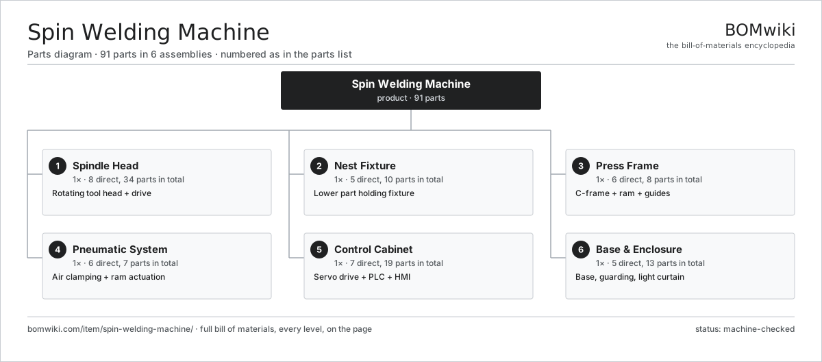
| # | Part | Qty | What it does |
|---|---|---|---|
| 1 | Spindle Head 8 parts | 1× | Rotating tool head + drive |
| 2 | Nest Fixture 5 parts | 1× | Lower part holding fixture |
| 3 | Press Frame 6 parts | 1× | C-frame + ram + guides |
| 4 | Pneumatic System 6 parts | 1× | Air clamping + ram actuation |
| 5 | Control Cabinet 7 parts | 1× | Servo drive + PLC + HMI |
| 6 | Base & Enclosure 5 parts | 1× | Base, guarding, light curtain |
3D model
No 3D model yet. Have a CAD file of this? Add a 3D model — STL renders right on this page; STEP, FreeCAD, and OpenSCAD sources are welcome too (openly licensed, like all 3D models on BOMwiki).
Build & assembly graph
expand / collapse · shared sub-assemblies converge · links to related products · est. labourTap an assembly to expand/collapse · tap a part to open it · use “Open page” for any node · drag to pan, scroll to zoom.
Bill of materials for Spin Welding Machine
6 top-level lines · 47 rows shown · 91 parts total · indented to 3 levels| # | Item / sub-assembly | Part no. | Qty/assy | Ext. qty | Parts | Type |
|---|---|---|---|---|---|---|
| 1 | Spindle Head 8 parts | swm-spindle-head | 1× | 1 | 34 | assembly |
| 1.1 | Servo Motor 4 parts | servo-motor | 1× | 1 | 24 | assembly |
| 1.1.1 | Stator Assembly 3 parts + deeper › | stator-assembly | 1× | 1 | 3 | assembly |
| 1.1.2 | Rotor Assembly 4 parts + deeper › | rotor-assembly | 1× | 1 | 19 | assembly |
| 1.1.3 | Encoder | encoder | 1× | 1 | · | part |
| 1.1.4 | Motor Housing | motor-housing | 1× | 1 | · | part |
| 1.2 | Spindle Shaft | swm-spindle-shaft | 1× | 1 | · | part |
| 1.3 | Ball Bearing | ball-bearing | 3× | 3 | · | part |
| 1.4 | Tool Chuck | swm-tool-chuck | 1× | 1 | · | part |
| 1.5 | Spindle Brake | swm-spindle-brake | 1× | 1 | · | part |
| 1.6 | Angular Encoder | swm-angular-encoder | 1× | 1 | · | part |
| 1.7 | Oil Seal | oil-seal | 2× | 2 | · | part |
| 1.8 | Fastener Set | fastener-set | 1× | 1 | · | part |
| 2 | Nest Fixture 5 parts | swm-nest-fixture | 1× | 1 | 10 | assembly |
| 2.1 | Nest Block | swm-nest-block | 1× | 1 | · | part |
| 2.2 | Anti-Rotation Pin | swm-anti-rotation-pin | 4× | 4 | · | part |
| 2.3 | Nest Clamp | swm-nest-clamp | 2× | 2 | · | part |
| 2.4 | Ejector Pin | swm-eject-pin | 2× | 2 | · | part |
| 2.5 | Fastener Set | fastener-set | 1× | 1 | · | part |
| 3 | Press Frame 6 parts | swm-press-frame | 1× | 1 | 8 | assembly |
| 3.1 | C-Frame | swm-c-frame | 1× | 1 | · | part |
| 3.2 | Weld Ram | swm-ram | 1× | 1 | · | part |
| 3.3 | Linear Guide Rail | linear-guide | 2× | 2 | · | part |
| 3.4 | Load Cell | swm-load-cell | 1× | 1 | · | part |
| 3.5 | Collapse Depth Sensor | swm-depth-sensor | 1× | 1 | · | part |
| 3.6 | Coil Spring | coil-spring | 2× | 2 | · | part |
| 4 | Pneumatic System 6 parts | swm-pneumatic-system | 1× | 1 | 7 | assembly |
| 4.1 | Ram Cylinder | swm-ram-cylinder | 1× | 1 | · | part |
| 4.2 | Proportional Valve | swm-proportional-valve | 1× | 1 | · | part |
| 4.3 | Air Regulator | swm-air-regulator | 1× | 1 | · | part |
| 4.4 | Pressure Sensor | pressure-sensor | 2× | 2 | · | part |
| 4.5 | Air Manifold | swm-air-manifold | 1× | 1 | · | part |
| 4.6 | O-Ring Set | oring-set | 1× | 1 | · | part |
| 5 | Control Cabinet 7 parts | swm-control-cabinet | 1× | 1 | 19 | assembly |
| 5.1 | Servo Drive | swm-servo-drive | 1× | 1 | · | part |
| 5.2 | PLC | swm-plc | 1× | 1 | · | part |
| 5.3 | LCD Panel | lcd-panel | 1× | 1 | · | part |
| 5.4 | Power Supply | power-supply | 1× | 1 | · | part |
| 5.5 | Relay | relay | 6× | 6 | · | part |
| 5.6 | Wire Bundle | wire-bundle | 1× | 1 | · | part |
| 5.7 | Connector | connector | 8× | 8 | · | part |
| 6 | Base & Enclosure 5 parts | swm-base-enclosure | 1× | 1 | 13 | assembly |
| 6.1 | Base Frame | swm-base-frame | 1× | 1 | · | part |
| 6.2 | Sheet Metal Panel | sheet-panel | 6× | 6 | · | part |
| 6.3 | Light Curtain | swm-light-curtain | 1× | 1 | · | part |
| 6.4 | Two-Hand Start | swm-two-hand-start | 1× | 1 | · | part |
| 6.5 | Leveling Foot | swm-leveling-foot | 4× | 4 | · | part |
Related products
same domain, ranked by shared parts Rubber Extrusion Line
524 parts · shares 21 with this page
Powder Coating Line
5,418 parts · shares 21 with this page
Wax Pattern Injection Press
107 parts · shares 21 with this page
Casting Fettling Machine
802 parts · shares 20 with this page
Shell Molding Machine
116 parts · shares 20 with this page
Rubber Extrusion Line
524 parts · shares 21 with this page
Powder Coating Line
5,418 parts · shares 21 with this page
Wax Pattern Injection Press
107 parts · shares 21 with this page
Casting Fettling Machine
802 parts · shares 20 with this page
Shell Molding Machine
116 parts · shares 20 with this page
Sourcing: possible vendors
Prices, MOQ, and lead times are algorithmic estimates, not quotes, and not claims about these companies. Company mappings are curated by keyword; est. price band $5k–$2M. How estimates work| Vendor | HQ | Specialty | MOQ | Lead time |
|---|---|---|---|---|
| atlascopco.com ↗ | Stockholm, SE | Compressors & industrial | 10 units | 12–20 wks |
|
🇦🇹Andritz
andritz.com ↗
|
Graz, AT | Process plants & machinery | 10 units | 12–20 wks |
| buhlergroup.com ↗ | Uzwil, CH | Food & materials processing | 10 units | 12–20 wks |
| gea.com ↗ | Düsseldorf, DE | Process technology | 10 units | 12–20 wks |
| mhi.com ↗ | Tokyo, JP | Heavy machinery | 10 units | 12–20 wks |
818-word article