Underwater Pelletizing System
ProductOverview
An underwater pelletizing system turns a continuous flow of molten polymer into uniform pellets by pushing the melt through a perforated die into a flooded chamber, where spinning knives slice each strand at the die face the instant it emerges. The water quenches the pellets, rounds them, and carries them away to be dried. It is the method of choice for high throughput and for resins that pelletize poorly any other way, and it is found at the end of polymer reactor lines, large compounding lines, and recycling lines. Its great advantage is clean spherical pellets at very high rates from one compact unit; its difficulty is startup, because the die face must stay hot enough to keep polymer flowing while sitting against cold water.
The melt arrives through the Bypass Valve to the Die Plate Assembly, where it is formed into strands. The Cutter Head slices them inside the Water Box, the Process Water System feeds and recirculates the water, the Centrifugal Dryer removes it, and the Pellet Transport carries the pellets on. The Control System runs the sequence, and the Frame and Trolley lets the whole front end retract for service.
Forming the strands
The Die Plate Assembly is the most thermally demanding part. The Die Plate is a hardened plate drilled with anywhere from a few dozen to several thousand small holes, and a tungsten-carbide Die Insert forms the wear face the knives sweep across. The whole challenge is heat: the die face sits in flowing water that wants to chill it, but if the holes drop below the polymer melt point the polymer freezes and plugs them. So the assembly is heavily heated by Die Heater cartridges, often supplemented by a Heating Channel carrying steam or hot oil, and isolated from the water by an Insulation Ring, while a Thermocouple watches the face temperature that decides whether the system runs clean or freezes off.
Cutting under water
The Cutter Head does the cutting. A Cutter Hub carries several Cutter Blade knives in Blade Holder holders, riding just at the die face on the Cutter Shaft turned by the Cutter Motor. As the melt extrudes, the blades sweep across the holes and shear off pellets flush with the face, and because this happens under water the pellets are quenched and rounded the instant they form. Pellet length is set by the relationship between throughput, blade count, and cutter speed, so the servo cutter is matched to extruder output for a consistent size. The blades wear against the hard die, so an Advance Mechanism keeps pushing them gently against the face to hold contact; too little force leaves tails on the pellets, too much wears blades and die fast. All of this is contained in the Water Box, whose Box Housing bolts to the die through an Box Seal and feeds water tangentially through the Water Inlet to swirl pellets out the Pellet Outlet. A Box Clamp swings the box clear for service.
Water, drying, and transport
The Process Water System does more than carry pellets; its temperature shapes them. Water from the Water Tank is driven by the Water Pump through the box and held at a set temperature by the Heat Exchanger, chosen per resin: too cold and crystalline resins like PET set with a rough surface, too hot and soft resins clump. A Water Filter removes fines so they do not recirculate, while a Flow Meter and Temperature Sensor confirm the conditions. The pellet slurry runs through the Pellet Transport, where a smooth Slurry Pipe and an Agglomerate Catcher deliver it to the Centrifugal Dryer. There a paddled Dryer Rotor flings the pellets up a Dryer Screen so water drains away and they leave nearly dry, and a Deduster lifts off fines before a Rotary Valve and Conveying Blower send them to storage.
Startup and control
Starting an underwater pelletizer is the hardest part of running one, and the Bypass Valve is what makes it manageable. At startup the die holes are cold and would freeze, so the Valve Spool, shifted by the Valve Cylinder, diverts the melt to a purge while the die heats and the operator confirms flow, then swings the melt to the die only when it is ready, with the cutter and water already running. The Control System sequences this automatically: a PLC runs the startup steps, the Temperature Controller holds the die face, the Blade Pressure Control sets blade contact, and the Variable Frequency Drive drives match the cutter to throughput, all from the HMI Panel. The Frame and Trolley carries the cutter and box on a Trolley that retracts on Linear Rail rails so the die face can be reached for a blade or die change.
Resins, variants, and use
The system handles almost any thermoplastic and excels at the hard cases: high-throughput polyolefins straight from a reactor, PET that must be quenched fast to stay clear, soft and tacky thermoplastic elastomers and hot melts that would stick on a strand cutter, and engineering resins like nylon. Throughput ranges from a small unit at a compounding line to giant reactor pelletizers running tens of tonnes an hour. Compared with the strand pelletizer built into a Twin-Screw Compounding Extruder, which cools strands in a bath before cutting, the underwater system cuts at the die face for cleaner spherical pellets and higher rates, at the cost of a more complex water and heating system and a more demanding startup. The closely related underwater eccentric and water-ring pelletizers trade some of that complexity for simpler handling at lower output.
Underwater Pelletizing System parts and their functions
9 top-level parts · 290 parts in total · full bill of materials below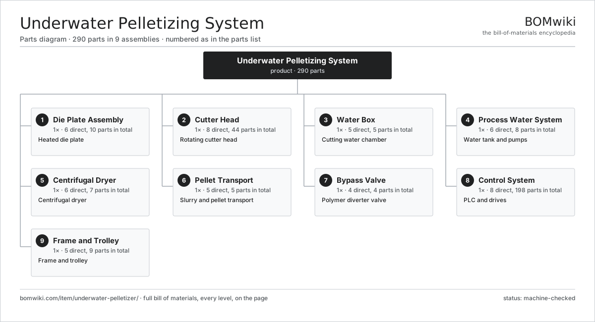
| # | Part | Qty | What it does |
|---|---|---|---|
| 1 | Die Plate Assembly 6 parts | 1× | Heated die plate |
| 2 | Cutter Head 8 parts | 1× | Rotating cutter head |
| 3 | Water Box 5 parts | 1× | Cutting water chamber |
| 4 | Process Water System 6 parts | 1× | Water tank and pumps |
| 5 | Centrifugal Dryer 6 parts | 1× | Centrifugal dryer |
| 6 | Pellet Transport 5 parts | 1× | Slurry and pellet transport |
| 7 | Bypass Valve 4 parts | 1× | Polymer diverter valve |
| 8 | Control System 8 parts | 1× | PLC and drives |
| 9 | Frame and Trolley 5 parts | 1× | Frame and trolley |
3D model
No 3D model yet. Have a CAD file of this? Add a 3D model — STL renders right on this page; STEP, FreeCAD, and OpenSCAD sources are welcome too (openly licensed, like all 3D models on BOMwiki).
Build & assembly graph
expand / collapse · shared sub-assemblies converge · links to related products · est. labourTap an assembly to expand/collapse · tap a part to open it · use “Open page” for any node · drag to pan, scroll to zoom.
Bill of materials for Underwater Pelletizing System
9 top-level lines · 79 rows shown · 290 parts total · indented to 3 levels| # | Item / sub-assembly | Part no. | Qty/assy | Ext. qty | Parts | Type |
|---|---|---|---|---|---|---|
| 1 | Die Plate Assembly 6 parts | uwp-die-plate-assembly | 1× | 1 | 10 | assembly |
| 1.1 | Die Plate | uwp-die-plate | 1× | 1 | · | part |
| 1.2 | Die Insert | uwp-die-insert | 1× | 1 | · | part |
| 1.3 | Die Heater | uwp-die-heater | 4× | 4 | · | part |
| 1.4 | Insulation Ring | uwp-insulation-ring | 1× | 1 | · | part |
| 1.5 | Thermocouple | uwp-thermocouple | 2× | 2 | · | part |
| 1.6 | Heating Channel | uwp-steam-channel | 1× | 1 | · | part |
| 2 | Cutter Head 8 parts | uwp-cutter-head | 1× | 1 | 44 | assembly |
| 2.1 | Cutter Hub | uwp-cutter-hub | 1× | 1 | · | part |
| 2.2 | Cutter Blade | uwp-cutter-blade | 6× | 6 | · | part |
| 2.3 | Blade Holder | uwp-blade-holder | 6× | 6 | · | part |
| 2.4 | Cutter Shaft | uwp-cutter-shaft | 1× | 1 | · | part |
| 2.5 | Cutter Motor 5 parts | uwp-cutter-motor | 1× | 1 | 26 | assembly |
| 2.5.1 | Stator Assembly 3 parts + deeper › | stator-assembly | 1× | 1 | 3 | assembly |
| 2.5.2 | Rotor Assembly 4 parts + deeper › | rotor-assembly | 1× | 1 | 19 | assembly |
| 2.5.3 | Motor Housing | motor-housing | 1× | 1 | · | part |
| 2.5.4 | Ball Bearing | ball-bearing | 2× | 2 | · | part |
| 2.5.5 | Encoder | encoder | 1× | 1 | · | part |
| 2.6 | Advance Mechanism | uwp-advance-mechanism | 1× | 1 | · | part |
| 2.7 | Ball Bearing | ball-bearing | 2× | 2 | · | part |
| 2.8 | Oil Seal | oil-seal | 1× | 1 | · | part |
| 3 | Water Box 5 parts | uwp-water-box | 1× | 1 | 5 | assembly |
| 3.1 | Box Housing | uwp-box-housing | 1× | 1 | · | part |
| 3.2 | Water Inlet | uwp-water-inlet | 1× | 1 | · | part |
| 3.3 | Pellet Outlet | uwp-pellet-outlet | 1× | 1 | · | part |
| 3.4 | Box Seal | uwp-box-seal | 1× | 1 | · | part |
| 3.5 | Box Clamp | uwp-clamp | 1× | 1 | · | part |
| 4 | Process Water System 6 parts | uwp-process-water-system | 1× | 1 | 8 | assembly |
| 4.1 | Water Tank | uwp-water-tank | 1× | 1 | · | part |
| 4.2 | Water Pump | uwp-water-pump | 2× | 2 | · | part |
| 4.3 | Heat Exchanger | uwp-heat-exchanger | 1× | 1 | · | part |
| 4.4 | Water Filter | uwp-water-filter | 1× | 1 | · | part |
| 4.5 | Temperature Sensor | uwp-temp-sensor | 2× | 2 | · | part |
| 4.6 | Flow Meter | uwp-flow-meter | 1× | 1 | · | part |
| 5 | Centrifugal Dryer 6 parts | uwp-dryer | 1× | 1 | 7 | assembly |
| 5.1 | Dryer Rotor | uwp-dryer-rotor | 1× | 1 | · | part |
| 5.2 | Dryer Screen | uwp-dryer-screen | 1× | 1 | · | part |
| 5.3 | Dryer Motor | uwp-dryer-motor | 1× | 1 | · | part |
| 5.4 | Dryer Housing | uwp-dryer-housing | 1× | 1 | · | part |
| 5.5 | Deduster | uwp-deduster | 1× | 1 | · | part |
| 5.6 | Ball Bearing | ball-bearing | 2× | 2 | · | part |
| 6 | Pellet Transport 5 parts | uwp-pellet-transport | 1× | 1 | 5 | assembly |
| 6.1 | Slurry Pipe | uwp-slurry-pipe | 1× | 1 | · | part |
| 6.2 | Agglomerate Catcher | uwp-agglomerate-catcher | 1× | 1 | · | part |
| 6.3 | Rotary Valve | uwp-rotary-valve | 1× | 1 | · | part |
| 6.4 | Conveying Blower | uwp-conveying-blower | 1× | 1 | · | part |
| 6.5 | Sample Chute | uwp-sample-chute | 1× | 1 | · | part |
| 7 | Bypass Valve 4 parts | uwp-bypass-valve | 1× | 1 | 4 | assembly |
| 7.1 | Valve Body | uwp-valve-body | 1× | 1 | · | part |
| 7.2 | Valve Spool | uwp-valve-spool | 1× | 1 | · | part |
| 7.3 | Valve Cylinder | uwp-valve-cylinder | 1× | 1 | · | part |
| 7.4 | Screen Pack | uwp-screen-pack | 1× | 1 | · | part |
| 8 | Control System 8 parts | uwp-control-system | 1× | 1 | 198 | assembly |
| 8.1 | PLC 4 parts | uwp-plc | 1× | 1 | 156 | assembly |
| 8.1.1 | Bare PCB | pcb-bare | 1× | 1 | · | part |
| 8.1.2 | Microcontroller | mcu | 1× | 1 | · | part |
| 8.1.3 | I/O Module | io-module | 4× | 4 | · | part |
| 8.1.4 | SMD Passive (R/C/L) | smd-passives | 150× | 150 | · | part |
| 8.2 | Variable Frequency Drive 4 parts | uwp-vfd | 2× | 2 | 5 | assembly |
| 8.2.1 | Bare PCB | pcb-bare | 1× | 2 | · | part |
| 8.2.2 | IGBT Power Module | igbt-module | 1× | 2 | · | part |
| 8.2.3 | DC-Link Capacitor | dc-link-cap | 2× | 4 | · | part |
| 8.2.4 | Microcontroller | mcu | 1× | 2 | · | part |
| 8.3 | HMI Panel 4 parts | uwp-hmi | 1× | 1 | 4 | assembly |
| 8.3.1 | LCD Panel | lcd-panel | 1× | 1 | · | part |
| 8.3.2 | Touch Digitizer | touch-digitizer | 1× | 1 | · | part |
| 8.3.3 | Bare PCB | pcb-bare | 1× | 1 | · | part |
| 8.3.4 | Microcontroller | mcu | 1× | 1 | · | part |
| 8.4 | Temperature Controller | uwp-temp-controller | 1× | 1 | · | part |
| 8.5 | Blade Pressure Control | uwp-blade-pressure-control | 1× | 1 | · | part |
| 8.6 | Power Supply | power-supply | 1× | 1 | · | part |
| 8.7 | Wire Bundle | wire-bundle | 1× | 1 | · | part |
| 8.8 | Connector | connector | 24× | 24 | · | part |
| 9 | Frame and Trolley 5 parts | uwp-frame | 1× | 1 | 9 | assembly |
| 9.1 | Frame Weldment | uwp-frame-weldment | 1× | 1 | · | part |
| 9.2 | Trolley | uwp-trolley | 1× | 1 | · | part |
| 9.3 | Linear Rail | uwp-linear-rail | 2× | 2 | · | part |
| 9.4 | Sheet Metal Panel | sheet-panel | 4× | 4 | · | part |
| 9.5 | Fastener Set | fastener-set | 1× | 1 | · | part |
Related products
same domain, ranked by shared parts Twin-Screw Compounding Extruder
595 parts · shares 23 with this page
WPC Profile Extrusion Line
422 parts · shares 22 with this page
Coil Coating Line
1,767 parts · shares 20 with this page
Twin-Screw Compounding Extruder
595 parts · shares 23 with this page
WPC Profile Extrusion Line
422 parts · shares 22 with this page
Coil Coating Line
1,767 parts · shares 20 with this page
 Injection Molding Machine
292 parts · shares 20 with this page
Injection Molding Machine
292 parts · shares 20 with this page
Sourcing: possible vendors
Prices, MOQ, and lead times are algorithmic estimates, not quotes, and not claims about these companies. Company mappings are curated by keyword; est. price band $5k–$2M. How estimates work| Vendor | HQ | Specialty | MOQ | Lead time |
|---|---|---|---|---|
| atlascopco.com ↗ | Stockholm, SE | Compressors & industrial | 10 units | 12–20 wks |
|
🇦🇹Andritz
andritz.com ↗
|
Graz, AT | Process plants & machinery | 10 units | 12–20 wks |
| buhlergroup.com ↗ | Uzwil, CH | Food & materials processing | 10 units | 12–20 wks |
| gea.com ↗ | Düsseldorf, DE | Process technology | 10 units | 12–20 wks |
| mhi.com ↗ | Tokyo, JP | Heavy machinery | 10 units | 12–20 wks |
978-word article