Casting Fettling Machine
ProductOverview
A casting fettling machine cleans up a rough casting after it leaves the mold. A fresh casting carries the gates and risers through which metal was fed, a line of flash where the mold halves met, and stubs where the runner system attached. Fettling, also called finishing or snagging, removes all of that and blends the surface so the part is ready for machining or shipment. The work was traditionally done by hand with a cutoff saw and a swing grinder, which is heavy, dusty and hard on the worker, so foundries now automate it in robotic cells. The machine grips each casting, cuts off the heavy gates, grinds the stubs and flash flush, and checks the result, all inside a sealed cabinet that contains the sparks and dust.
The cell is built inside a sealed Machine Enclosure. A Handling Robot handles the casting against a fixed Grinding Head and a Cutoff Station, parts are presented on a Fixture Table, the Vision and Gauging system finds and checks them, the Dust and Swarf Extraction clears the dust, and the Control System runs the program.
The handling robot
The defining choice in robotic fettling is to move the part to the tool rather than the tool to the part. The Handling Robot grips the casting in a Casting Gripper and presses it against the fixed grinding wheel and cutoff disc along a programmed path. This works because the grinding tools are heavy and need rigid mounting, while the casting is the lighter, more variable item. The catch is that castings vary in size from one to the next, so a fixed path would grind some too deep and others too little. The answer is a Force-Torque Sensor in the robot wrist that holds the contact force constant: the robot follows the surface and pushes with a set force rather than tracking a rigid line, so it removes stock to a consistent result whatever the starting stock. The Robot Controller runs both the path and this force loop.
Cutoff and grinding
Two kinds of metal removal happen in the cell. The Cutoff Station does the heavy work first: a Cutoff Wheel, a reinforced abrasive disc spun fast by the Cutoff Motor, severs the thick gates and risers from the casting body, fed in at controlled force by the Feed Cylinder. Then the Grinding Head blends what is left. Its Grinding Spindle turns a Grinding Wheel of zirconia-alumina grit that grinds the stubs flush and dresses the parting flash, while a Belt Head handles larger flatter surfaces. A Wheel Dresser trues the wheel between parts so it keeps cutting true as it wears. Heavy cutting first then fine blending keeps cycle time down, since the slow grinding wheel is not asked to remove a whole riser.
Fixturing and flow
To keep the robot grinding rather than waiting, the Fixture Table is an indexing table with two or more Fixture Nest nests. While the robot fettles the casting in the grind position, an operator or loader places the next rough casting in the load position; the Index Drive then turns the table to swap them. The Part Clamp clamps hold each casting the same way every cycle so the program and the gauging stay valid. This load-while-grinding flow is what lets a single cell keep up with a molding line.
Vision and gauging
Rough castings do not arrive perfectly placed, so the Vision and Gauging system locates each one before the robot touches it. A Vision Camera finds the casting and the gates to be removed, a Laser Scanner profiles the actual surface so the grind path can be adapted to this part's real stock, and after grinding a Touch Probe checks that flash and stubs are within tolerance. The Vision Controller ties these together and passes or fails each casting, so defective parts are caught in the cell rather than at final inspection. This closed measurement loop is what makes unattended fettling trustworthy.
Dust, safety and use
Grinding iron and steel throws sparks and a fine metal dust that can deflagrate, so the Dust and Swarf Extraction is built for that hazard. A Dust Hood captures dust at the wheel, a Spark Arrestor quenches sparks, and a Wet Collector traps the fines safely in water rather than a dry bag, while a Swarf Auger clears ground-off metal from the cabinet floor. The whole cell sits in a sealed Machine Enclosure with Door Interlock interlocks and E-Stop Button buttons so no one is near the wheels while they turn. The cell is run by the PLC and set up on the Operator HMI, where a grind program is stored for each casting. Cells range from single-robot units finishing one part family to multi-robot lines where one robot cuts off gates and a second grinds and gauges, all fed from the same molding and shakeout line.
Casting Fettling Machine parts and their functions
8 top-level parts · 802 parts in total · full bill of materials below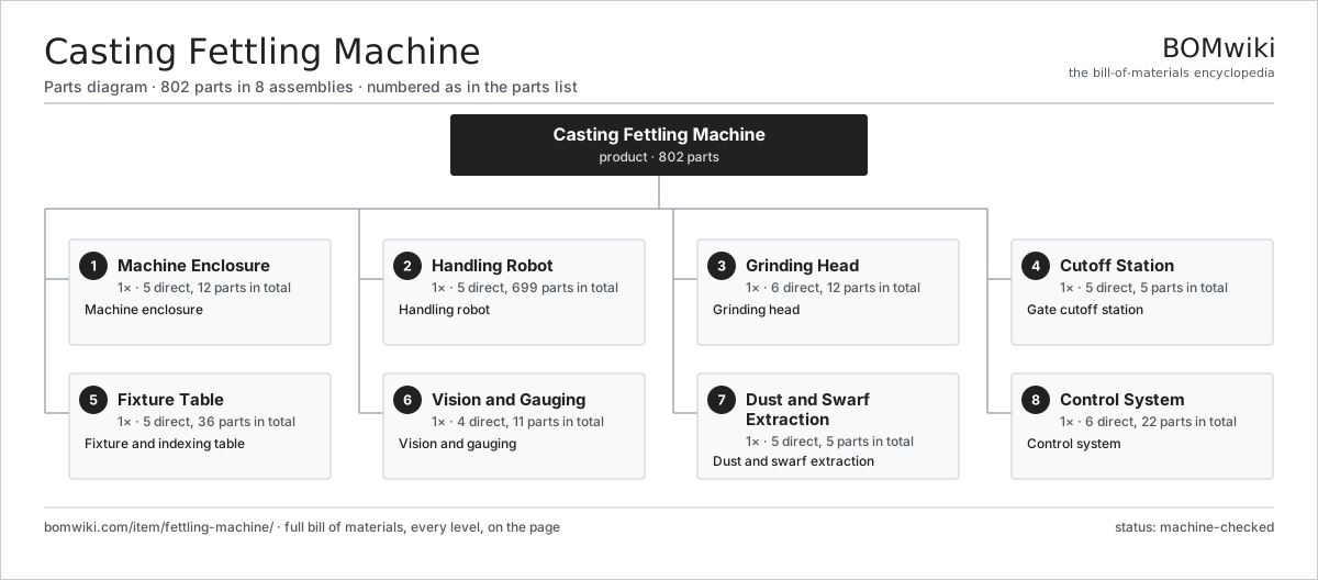
| # | Part | Qty | What it does |
|---|---|---|---|
| 1 | Machine Enclosure 5 parts | 1× | Machine enclosure |
| 2 | Handling Robot 5 parts | 1× | Handling robot |
| 3 | Grinding Head 6 parts | 1× | Grinding head |
| 4 | Cutoff Station 5 parts | 1× | Gate cutoff station |
| 5 | Fixture Table 5 parts | 1× | Fixture and indexing table |
| 6 | Vision and Gauging 4 parts | 1× | Vision and gauging |
| 7 | Dust and Swarf Extraction 5 parts | 1× | Dust and swarf extraction |
| 8 | Control System 6 parts | 1× | Control system |
3D model
No 3D model yet. Have a CAD file of this? Add a 3D model — STL renders right on this page; STEP, FreeCAD, and OpenSCAD sources are welcome too (openly licensed, like all 3D models on BOMwiki).
Build & assembly graph
expand / collapse · shared sub-assemblies converge · links to related products · est. labourTap an assembly to expand/collapse · tap a part to open it · use “Open page” for any node · drag to pan, scroll to zoom.
Bill of materials for Casting Fettling Machine
8 top-level lines · 79 rows shown · 802 parts total · indented to 3 levels| # | Item / sub-assembly | Part no. | Qty/assy | Ext. qty | Parts | Type |
|---|---|---|---|---|---|---|
| 1 | Machine Enclosure 5 parts | fettling-machine-enclosure | 1× | 1 | 12 | assembly |
| 1.1 | Enclosure Frame | fettling-machine-enclosure-frame | 1× | 1 | · | part |
| 1.2 | Access Door | fettling-machine-access-door | 2× | 2 | · | part |
| 1.3 | Spark Liner | fettling-machine-spark-liner | 1× | 1 | · | part |
| 1.4 | Door Interlock | fettling-machine-door-switch | 2× | 2 | · | part |
| 1.5 | Sheet Metal Panel | sheet-panel | 6× | 6 | · | part |
| 2 | Handling Robot 5 parts | fettling-machine-robot | 1× | 1 | 699 | assembly |
| 2.1 | Robot Arm | fettling-machine-robot-arm | 1× | 1 | · | part |
| 2.2 | Casting Gripper 3 parts | fettling-machine-gripper | 1× | 1 | 4 | assembly |
| 2.2.1 | Gripper Jaw | fettling-machine-gripper-jaw | 2× | 2 | · | part |
| 2.2.2 | Gripper Cylinder | fettling-machine-gripper-cylinder | 1× | 1 | · | part |
| 2.2.3 | O-Ring Set | oring-set | 1× | 1 | · | part |
| 2.3 | Force-Torque Sensor | fettling-machine-force-sensor | 1× | 1 | · | part |
| 2.4 | Servo Motor 4 parts | servo-motor | 6× | 6 | 24 | assembly |
| 2.4.1 | Stator Assembly 3 parts + deeper › | stator-assembly | 1× | 6 | 3 | assembly |
| 2.4.2 | Rotor Assembly 4 parts + deeper › | rotor-assembly | 1× | 6 | 19 | assembly |
| 2.4.3 | Encoder | encoder | 1× | 6 | · | part |
| 2.4.4 | Motor Housing | motor-housing | 1× | 6 | · | part |
| 2.5 | Robot Controller 4 parts | fettling-machine-robot-controller | 1× | 1 | 549 | assembly |
| 2.5.1 | Bare PCB | pcb-bare | 1× | 1 | · | part |
| 2.5.2 | Microcontroller | mcu | 1× | 1 | · | part |
| 2.5.3 | Servo Drive 4 parts + deeper › | servo-drive | 6× | 6 | 91 | assembly |
| 2.5.4 | Power Supply | power-supply | 1× | 1 | · | part |
| 3 | Grinding Head 6 parts | fettling-machine-grinding-head | 1× | 1 | 12 | assembly |
| 3.1 | Grinding Spindle | fettling-machine-grind-spindle | 1× | 1 | · | part |
| 3.2 | Grinding Wheel 3 parts | fettling-machine-grind-wheel | 1× | 1 | 4 | assembly |
| 3.2.1 | Abrasive Grain | fettling-machine-abrasive-grain | 1× | 1 | · | part |
| 3.2.2 | Bond Resin | fettling-machine-bond-resin | 1× | 1 | · | part |
| 3.2.3 | Reinforcement Mesh | fettling-machine-mesh-disc | 2× | 2 | · | part |
| 3.3 | Belt Head | fettling-machine-belt-head | 1× | 1 | · | part |
| 3.4 | Spindle Motor | fettling-machine-spindle-motor | 1× | 1 | · | part |
| 3.5 | Wheel Dresser | fettling-machine-wheel-dresser | 1× | 1 | · | part |
| 3.6 | Ball Bearing | ball-bearing | 4× | 4 | · | part |
| 4 | Cutoff Station 5 parts | fettling-machine-cutoff-station | 1× | 1 | 5 | assembly |
| 4.1 | Cutoff Wheel | fettling-machine-cutoff-wheel | 1× | 1 | · | part |
| 4.2 | Cutoff Motor | fettling-machine-cutoff-motor | 1× | 1 | · | part |
| 4.3 | Cutoff Arm | fettling-machine-cutoff-arm | 1× | 1 | · | part |
| 4.4 | Feed Cylinder | fettling-machine-cutoff-cylinder | 1× | 1 | · | part |
| 4.5 | Coil Spring | coil-spring | 1× | 1 | · | part |
| 5 | Fixture Table 5 parts | fettling-machine-fixture-table | 1× | 1 | 36 | assembly |
| 5.1 | Index Table | fettling-machine-index-table | 1× | 1 | · | part |
| 5.2 | Fixture Nest | fettling-machine-fixture-nest | 2× | 2 | · | part |
| 5.3 | Index Drive 3 parts | fettling-machine-index-drive | 1× | 1 | 27 | assembly |
| 5.3.1 | Servo Motor 4 parts + deeper › | servo-motor | 1× | 1 | 24 | assembly |
| 5.3.2 | Helical Gear Pair | gear-pair | 1× | 1 | · | part |
| 5.3.3 | Ball Bearing | ball-bearing | 2× | 2 | · | part |
| 5.4 | Part Clamp | fettling-machine-clamp | 4× | 4 | · | part |
| 5.5 | Linear Guide Rail | linear-guide | 2× | 2 | · | part |
| 6 | Vision and Gauging 4 parts | fettling-machine-vision | 1× | 1 | 11 | assembly |
| 6.1 | Vision Camera 3 parts | fettling-machine-vision-camera | 2× | 2 | 3 | assembly |
| 6.1.1 | Bare PCB | pcb-bare | 1× | 2 | · | part |
| 6.1.2 | Image Sensor | fettling-machine-image-sensor | 1× | 2 | · | part |
| 6.1.3 | Camera Lens | fettling-machine-cam-lens | 1× | 2 | · | part |
| 6.2 | Laser Scanner | fettling-machine-laser-scanner | 1× | 1 | · | part |
| 6.3 | Touch Probe | fettling-machine-touch-probe | 1× | 1 | · | part |
| 6.4 | Vision Controller 3 parts | fettling-machine-vision-controller | 1× | 1 | 3 | assembly |
| 6.4.1 | Bare PCB | pcb-bare | 1× | 1 | · | part |
| 6.4.2 | Microcontroller | mcu | 1× | 1 | · | part |
| 6.4.3 | SMD Passive (R/C/L) | smd-passives | 1× | 1 | · | part |
| 7 | Dust and Swarf Extraction 5 parts | fettling-machine-dust-system | 1× | 1 | 5 | assembly |
| 7.1 | Dust Hood | fettling-machine-dust-hood | 1× | 1 | · | part |
| 7.2 | Spark Arrestor | fettling-machine-spark-arrestor | 1× | 1 | · | part |
| 7.3 | Wet Collector | fettling-machine-wet-collector | 1× | 1 | · | part |
| 7.4 | Swarf Auger | fettling-machine-swarf-auger | 1× | 1 | · | part |
| 7.5 | Extraction Fan | fettling-machine-dust-fan | 1× | 1 | · | part |
| 8 | Control System 6 parts | fettling-machine-control | 1× | 1 | 22 | assembly |
| 8.1 | PLC 4 parts | fettling-machine-plc | 1× | 1 | 7 | assembly |
| 8.1.1 | Bare PCB | pcb-bare | 1× | 1 | · | part |
| 8.1.2 | Microcontroller | mcu | 1× | 1 | · | part |
| 8.1.3 | Relay | relay | 4× | 4 | · | part |
| 8.1.4 | SMD Passive (R/C/L) | smd-passives | 1× | 1 | · | part |
| 8.2 | Operator HMI 3 parts | fettling-machine-hmi | 1× | 1 | 3 | assembly |
| 8.2.1 | LCD Panel | lcd-panel | 1× | 1 | · | part |
| 8.2.2 | Microcontroller | mcu | 1× | 1 | · | part |
| 8.2.3 | Bare PCB | pcb-bare | 1× | 1 | · | part |
| 8.3 | Power Supply | power-supply | 1× | 1 | · | part |
| 8.4 | E-Stop Button | fettling-machine-estop | 2× | 2 | · | part |
| 8.5 | Wire Bundle | wire-bundle | 1× | 1 | · | part |
| 8.6 | Connector | connector | 8× | 8 | · | part |
Related products
same domain, ranked by shared parts Investment Casting Shell Line
869 parts · shares 26 with this page
Investment Casting Shell Line
869 parts · shares 26 with this page
 Injection Molding Machine
292 parts · shares 24 with this page
Injection Molding Machine
292 parts · shares 24 with this page
 Continuous Galvanizing Line
1,296 parts · shares 22 with this page
Coil Coating Line
1,767 parts · shares 22 with this page
Continuous Galvanizing Line
1,296 parts · shares 22 with this page
Coil Coating Line
1,767 parts · shares 22 with this page
 Dynamic Balancing Machine
573 parts · shares 19 with this page
Cast Film Extrusion Line
406 parts · shares 22 with this page
Dynamic Balancing Machine
573 parts · shares 19 with this page
Cast Film Extrusion Line
406 parts · shares 22 with this page
Sourcing: possible vendors
Prices, MOQ, and lead times are algorithmic estimates, not quotes, and not claims about these companies. Company mappings are curated by keyword; est. price band $5k–$2M. How estimates work| Vendor | HQ | Specialty | MOQ | Lead time |
|---|---|---|---|---|
| atlascopco.com ↗ | Stockholm, SE | Compressors & industrial | 10 units | 12–20 wks |
|
🇦🇹Andritz
andritz.com ↗
|
Graz, AT | Process plants & machinery | 10 units | 12–20 wks |
| buhlergroup.com ↗ | Uzwil, CH | Food & materials processing | 10 units | 12–20 wks |
| gea.com ↗ | Düsseldorf, DE | Process technology | 10 units | 12–20 wks |
| mhi.com ↗ | Tokyo, JP | Heavy machinery | 10 units | 12–20 wks |
882-word article