Stretch Blow Molding Machine
ProductOverview
A stretch blow molding machine makes PET bottles by reheating an injection-molded preform, stretching it lengthwise with a rod, and blowing it outward with high-pressure air until it fills a bottle mold. This is the standard process for water, soft drink, juice and household bottles. The Stretch Blow Molding Machine does not melt plastic; it works the PET in its rubbery state, just above the glass transition, where the polymer chains can be oriented in two directions at once.
That biaxial orientation is the whole point. Stretching the PET both axially and radially aligns the polymer chains, which makes the bottle far stronger, clearer, and more gas-tight than an unoriented wall of the same weight. A carbonated drink bottle would burst without it. The two-stage version covered here takes in cold preforms made elsewhere, so a single machine type can run any neck and any bottle shape just by changing molds and reheat settings.
Preform feeding
Preforms arrive in bulk and the Preform Feeder orients them. A Feed Elevator lifts loose preforms from the Preform Hopper to a Roller Sorter, where counter-rotating rollers catch each one by its support ring and let it hang neck-up. Oriented preforms slide down the Feed Rail by the neck ring and a Transfer Starwheel hands them onto the oven, all without touching the body that is about to be heated and blown.
Infrared reheat oven
The Infrared Heating Oven is a tunnel of Infrared Lamp banks. Each preform rides through on a Spinning Mandrel that grips it by the neck and rotates it, so the Infrared Lamp energy reaches every side evenly. Near-infrared lamps are used because that wavelength penetrates the PET wall and heats it through rather than only at the surface. Reflector Panel panels behind the preforms send stray heat back, Oven Blower units even out the temperature through the wall thickness, and a Pyrometer reads the skin temperature to close the loop on lamp power.
One zone must stay cold: the Neck Cooling Shield shield protects the finished thread, which was already molded into the preform and must not soften or it will lose its seal. The target body temperature is roughly 95-115 C, hot enough to stretch, cool enough to hold detail.
Stretch and two-stage blow
Heated preforms pass to the Rotary Blow Wheel, a rotating carousel that carries the molds and stretch-blow stations continuously past the load and discharge points. The Wheel Drive turns it, a Cam Track times the mechanical motions, and a Rotary Union feeds high-pressure air and coolant onto the turning wheel.
At each Stretch-Blow Station the forming happens in a precise sequence. First the Stretch Rod, driven by the Stretch Rod Servo, pushes down inside the preform and stretches it axially to the base of the mold, holding the bottle centered. As it stretches, the Pre-Blow Valve admits pre-blow air at 5-15 bar to start the radial expansion in a controlled way. Then the High-Pressure Blow Valve admits high-pressure air at 25-40 bar through the Blow Nozzle, pressing the bottle hard into the cavity to reproduce every detail, the threads-to-base proportions, the label panel and the base. Coordinating the rod speed with the pre-blow timing controls how material distributes, which is what determines whether the corners and base are thick enough.
High-pressure air and recovery
Final blow needs clean dry air at up to 40 bar, supplied by the High-Pressure Air System system. A multi-stage High-Pressure Compressor with its Intercooler produces the pressure, a Air Dryer removes moisture that would otherwise fog the bottle, and a High-Pressure Receiver buffers demand. Because high-pressure air is the largest energy cost in the process, the Exhaust Recovery Valve routes spent blow air into a Recovery Tank and reuses it as pre-blow air, cutting compressor load substantially.
Molds, discharge and control
The Bottle Mold Set gives the bottle its shape. Two hinged Mold Shell halves form the body, a Base Mold cup forms the base, and the Mold Lock lock holds the shells shut against 40 bar. A Mold Cooling Channel circuit runs chilled water through the cavity so the stretched PET sets quickly and the bottle keeps its dimensions when it leaves the mold.
Finished bottles are lifted out by the Discharge Starwheel and moved by the neck on an Air Conveyor, with a Reject Gate removing any flagged by inspection. The whole machine is timed by the Control System: a Motion PLC synchronizes oven heat, wheel rotation, stretch and the two blow stages, Servo Drive units run the wheel, feed and stretch servos, and the operator sets recipes on the HMI Touch Panel panel. The Machine Frame and Guarding carries it all behind interlocked guarding.
Variants
Single-stage machines injection-mold the preform and blow it in one continuous line, keeping the residual heat of molding instead of reheating, which suits short runs and premium containers. The reheat two-stage machine described here dominates high-volume beverage production because it decouples preform supply from blowing. Linear shuttle machines blow a row of molds back and forth and serve mid-range output, while rotary wheel machines reach the highest speeds. Heat-set versions hold the mold hot to crystallize the PET for hot-fill products like juice, and integrated blow-fill-cap systems combine the blower with the filler so bottles are never stored empty.
Stretch Blow Molding Machine parts and their functions
9 top-level parts · 460 parts in total · full bill of materials below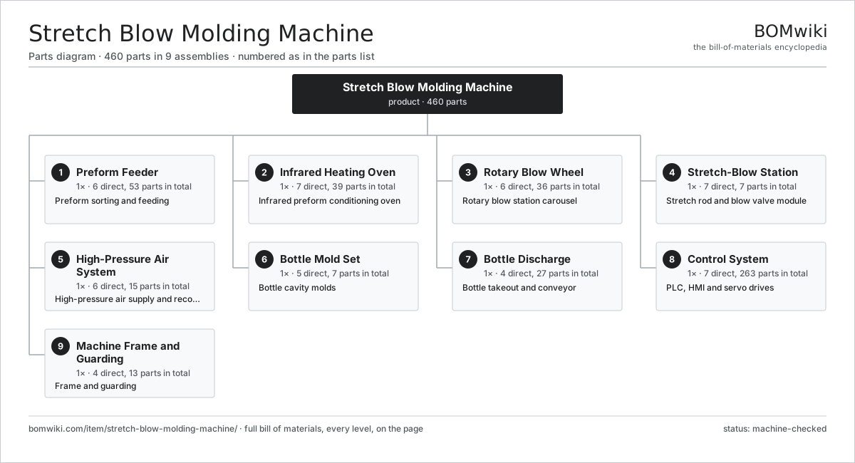
| # | Part | Qty | What it does |
|---|---|---|---|
| 1 | Preform Feeder 6 parts | 1× | Preform sorting and feeding |
| 2 | Infrared Heating Oven 7 parts | 1× | Infrared preform conditioning oven |
| 3 | Rotary Blow Wheel 6 parts | 1× | Rotary blow station carousel |
| 4 | Stretch-Blow Station 7 parts | 1× | Stretch rod and blow valve module |
| 5 | High-Pressure Air System 6 parts | 1× | High-pressure air supply and recovery |
| 6 | Bottle Mold Set 5 parts | 1× | Bottle cavity molds |
| 7 | Bottle Discharge 4 parts | 1× | Bottle takeout and conveyor |
| 8 | Control System 7 parts | 1× | PLC, HMI and servo drives |
| 9 | Machine Frame and Guarding 4 parts | 1× | Frame and guarding |
3D model
No 3D model yet. Have a CAD file of this? Add a 3D model — STL renders right on this page; STEP, FreeCAD, and OpenSCAD sources are welcome too (openly licensed, like all 3D models on BOMwiki).
Build & assembly graph
expand / collapse · shared sub-assemblies converge · links to related products · est. labourTap an assembly to expand/collapse · tap a part to open it · use “Open page” for any node · drag to pan, scroll to zoom.
Bill of materials for Stretch Blow Molding Machine
9 top-level lines · 85 rows shown · 460 parts total · indented to 3 levels| # | Item / sub-assembly | Part no. | Qty/assy | Ext. qty | Parts | Type |
|---|---|---|---|---|---|---|
| 1 | Preform Feeder 6 parts | sbm-preform-feeder | 1× | 1 | 53 | assembly |
| 1.1 | Preform Hopper | sbm-preform-hopper | 1× | 1 | · | part |
| 1.2 | Feed Elevator | sbm-feed-elevator | 1× | 1 | · | part |
| 1.3 | Roller Sorter | sbm-roller-sorter | 1× | 1 | · | part |
| 1.4 | Feed Rail | sbm-feed-rail | 1× | 1 | · | part |
| 1.5 | Transfer Starwheel | sbm-transfer-starwheel | 1× | 1 | · | part |
| 1.6 | Servo Motor 4 parts | servo-motor | 2× | 2 | 24 | assembly |
| 1.6.1 | Stator Assembly 3 parts + deeper › | stator-assembly | 1× | 2 | 3 | assembly |
| 1.6.2 | Rotor Assembly 4 parts + deeper › | rotor-assembly | 1× | 2 | 19 | assembly |
| 1.6.3 | Encoder | encoder | 1× | 2 | · | part |
| 1.6.4 | Motor Housing | motor-housing | 1× | 2 | · | part |
| 2 | Infrared Heating Oven 7 parts | sbm-heating-oven | 1× | 1 | 39 | assembly |
| 2.1 | Infrared Lamp | sbm-ir-lamp | 24× | 24 | · | part |
| 2.2 | Spinning Mandrel | sbm-spinning-mandrel | 1× | 1 | · | part |
| 2.3 | Oven Conveyor Chain | sbm-oven-chain | 1× | 1 | · | part |
| 2.4 | Reflector Panel | sbm-reflector-panel | 8× | 8 | · | part |
| 2.5 | Neck Cooling Shield | sbm-neck-cooling | 1× | 1 | · | part |
| 2.6 | Pyrometer | sbm-pyrometer | 2× | 2 | · | part |
| 2.7 | Oven Blower | sbm-oven-blower | 2× | 2 | · | part |
| 3 | Rotary Blow Wheel 6 parts | sbm-blow-wheel | 1× | 1 | 36 | assembly |
| 3.1 | Wheel Frame | sbm-wheel-frame | 1× | 1 | · | part |
| 3.2 | Wheel Drive 4 parts | sbm-wheel-drive | 1× | 1 | 28 | assembly |
| 3.2.1 | Servo Motor 4 parts + deeper › | servo-motor | 1× | 1 | 24 | assembly |
| 3.2.2 | Gearbox Housing | gearbox-housing | 1× | 1 | · | part |
| 3.2.3 | Helical Gear Pair | gear-pair | 1× | 1 | · | part |
| 3.2.4 | Ball Bearing | ball-bearing | 2× | 2 | · | part |
| 3.3 | Cam Track | sbm-cam-track | 1× | 1 | · | part |
| 3.4 | Rotary Union | sbm-rotary-union | 1× | 1 | · | part |
| 3.5 | Infeed Starwheel | sbm-infeed-starwheel | 1× | 1 | · | part |
| 3.6 | Ball Bearing | ball-bearing | 4× | 4 | · | part |
| 4 | Stretch-Blow Station 7 parts | sbm-stretch-blow-station | 1× | 1 | 7 | assembly |
| 4.1 | Stretch Rod | sbm-stretch-rod | 1× | 1 | · | part |
| 4.2 | Stretch Rod Servo | sbm-stretch-servo | 1× | 1 | · | part |
| 4.3 | Pre-Blow Valve | sbm-prefill-valve | 1× | 1 | · | part |
| 4.4 | High-Pressure Blow Valve | sbm-blow-valve-hp | 1× | 1 | · | part |
| 4.5 | Exhaust Recovery Valve | sbm-exhaust-recovery-valve | 1× | 1 | · | part |
| 4.6 | Blow Nozzle | sbm-blow-nozzle | 1× | 1 | · | part |
| 4.7 | Pressure Sensor | pressure-sensor | 1× | 1 | · | part |
| 5 | High-Pressure Air System 6 parts | sbm-high-pressure-air | 1× | 1 | 15 | assembly |
| 5.1 | High-Pressure Compressor 5 parts | sbm-hp-compressor | 1× | 1 | 8 | assembly |
| 5.1.1 | Pump Drive Motor | lsr-pump-motor | 1× | 1 | · | part |
| 5.1.2 | Compressor Block | sbm-compressor-block | 1× | 1 | · | part |
| 5.1.3 | Intercooler | sbm-intercooler | 1× | 1 | · | part |
| 5.1.4 | Ball Bearing | ball-bearing | 2× | 2 | · | part |
| 5.1.5 | O-Ring Set | oring-set | 3× | 3 | · | part |
| 5.2 | Air Dryer | sbm-air-dryer | 1× | 1 | · | part |
| 5.3 | High-Pressure Receiver | sbm-hp-receiver | 1× | 1 | · | part |
| 5.4 | Recovery Tank | sbm-recovery-tank | 1× | 1 | · | part |
| 5.5 | Coalescing Filter | sbm-air-filter | 2× | 2 | · | part |
| 5.6 | Pressure Sensor | pressure-sensor | 2× | 2 | · | part |
| 6 | Bottle Mold Set 5 parts | sbm-mold-set | 1× | 1 | 7 | assembly |
| 6.1 | Mold Shell | sbm-mold-shell | 2× | 2 | · | part |
| 6.2 | Base Mold | sbm-base-mold | 1× | 1 | · | part |
| 6.3 | Mold Cooling Channel | sbm-mold-cooling-channel | 1× | 1 | · | part |
| 6.4 | Mold Lock | sbm-mold-clamp | 1× | 1 | · | part |
| 6.5 | O-Ring Set | oring-set | 2× | 2 | · | part |
| 7 | Bottle Discharge 4 parts | sbm-bottle-discharge | 1× | 1 | 27 | assembly |
| 7.1 | Discharge Starwheel | sbm-discharge-starwheel | 1× | 1 | · | part |
| 7.2 | Air Conveyor | sbm-air-conveyor | 1× | 1 | · | part |
| 7.3 | Reject Gate | sbm-reject-gate | 1× | 1 | · | part |
| 7.4 | Servo Motor 4 parts | servo-motor | 1× | 1 | 24 | assembly |
| 7.4.1 | Stator Assembly 3 parts + deeper › | stator-assembly | 1× | 1 | 3 | assembly |
| 7.4.2 | Rotor Assembly 4 parts + deeper › | rotor-assembly | 1× | 1 | 19 | assembly |
| 7.4.3 | Encoder | encoder | 1× | 1 | · | part |
| 7.4.4 | Motor Housing | motor-housing | 1× | 1 | · | part |
| 8 | Control System 7 parts | sbm-control-system | 1× | 1 | 263 | assembly |
| 8.1 | Motion PLC 3 parts | sbm-plc | 1× | 1 | 153 | assembly |
| 8.1.1 | Bare PCB | pcb-bare | 1× | 1 | · | part |
| 8.1.2 | Microcontroller | mcu | 2× | 2 | · | part |
| 8.1.3 | SMD Passive (R/C/L) | smd-passives | 150× | 150 | · | part |
| 8.2 | HMI Touch Panel 4 parts | lsr-hmi | 1× | 1 | 93 | assembly |
| 8.2.1 | LCD Panel | lcd-panel | 1× | 1 | · | part |
| 8.2.2 | Bare PCB | pcb-bare | 1× | 1 | · | part |
| 8.2.3 | Microcontroller | mcu | 1× | 1 | · | part |
| 8.2.4 | SMD Passive (R/C/L) | smd-passives | 90× | 90 | · | part |
| 8.3 | Servo Drive | lsr-servo-drive | 3× | 3 | · | part |
| 8.4 | Power Supply | power-supply | 1× | 1 | · | part |
| 8.5 | I/O Module | lsr-io-module | 2× | 2 | · | part |
| 8.6 | Relay | relay | 10× | 10 | · | part |
| 8.7 | Control Cabinet | lsr-control-cabinet | 1× | 1 | · | part |
| 9 | Machine Frame and Guarding 4 parts | sbm-machine-frame | 1× | 1 | 13 | assembly |
| 9.1 | Base Frame | sbm-base-frame | 1× | 1 | · | part |
| 9.2 | Safety Door | lsr-safety-door | 3× | 3 | · | part |
| 9.3 | Leveling Foot | lsr-leveling-foot | 8× | 8 | · | part |
| 9.4 | Fastener Set | fastener-set | 1× | 1 | · | part |
Related products
same domain, ranked by shared parts Reaction Injection Molding Machine
457 parts · shares 26 with this page
Automated Paint Spray Line
2,003 parts · shares 20 with this page
Coil Coating Line
1,767 parts · shares 20 with this page
Electrocoating Line
2,977 parts · shares 20 with this page
Reaction Injection Molding Machine
457 parts · shares 26 with this page
Automated Paint Spray Line
2,003 parts · shares 20 with this page
Coil Coating Line
1,767 parts · shares 20 with this page
Electrocoating Line
2,977 parts · shares 20 with this page
 Industrial Parts Washer
423 parts · shares 20 with this page
Industrial Parts Washer
423 parts · shares 20 with this page
Sourcing: possible vendors
Prices, MOQ, and lead times are algorithmic estimates, not quotes, and not claims about these companies. Company mappings are curated by keyword; est. price band $5k–$2M. How estimates work| Vendor | HQ | Specialty | MOQ | Lead time |
|---|---|---|---|---|
| atlascopco.com ↗ | Stockholm, SE | Compressors & industrial | 10 units | 12–20 wks |
|
🇦🇹Andritz
andritz.com ↗
|
Graz, AT | Process plants & machinery | 10 units | 12–20 wks |
| buhlergroup.com ↗ | Uzwil, CH | Food & materials processing | 10 units | 12–20 wks |
| gea.com ↗ | Düsseldorf, DE | Process technology | 10 units | 12–20 wks |
| mhi.com ↗ | Tokyo, JP | Heavy machinery | 10 units | 12–20 wks |
945-word article