Twin-Screw Compounding Extruder
ProductOverview
A twin-screw compounding extruder is the workhorse of the plastics industry, the machine that turns raw polymer into the engineered grades that get molded and extruded into products. It does not make a finished part; it makes pellets of a custom recipe by melting a base polymer and mixing in fillers, reinforcing fibers, pigments, flame retardants, impact modifiers, and stabilizers in exact ratios, continuously. Almost every filled, colored, or reinforced plastic on the market, glass-filled nylon, color masterbatch, flame-retardant cable compound, was made on a machine like this.
The defining feature is two co-rotating, intermeshing screws built from interchangeable elements. By stacking conveying, kneading, and mixing elements in the right order, the same machine can be configured for gentle blending or intensive dispersion. The Feed System meters every ingredient by weight, the Process Section melts and mixes them, the Drive Train turns the screws, the Degassing System strips out volatiles, and the Die and Pelletizer turns the compound into pellets. The Barrel Temperature System system and the Control System hold the recipe, all mounted on the Machine Base.
Feeding by weight
Compounding is recipe work, so the Feed System meters ingredients by mass rather than volume. The Main Feeder is a loss-in-weight feeder: it sits on a Load Cell and adjusts its Feed Screw speed to hold a constant mass rate as the hopper empties, with a Hopper Agitator keeping powder flowing. Each Additive Feeder does the same for a pigment or stabilizer, and a Liquid Injector pumps oils straight into the melt. Abrasive or heat-sensitive fillers like glass fiber and talc are added through a Side Feeder partway down the barrel, after the polymer has melted, so the fiber is coated and distributed rather than ground up and over-sheared in the feed zone. The ratio of all these streams is what defines the compound, and the controller holds it continuously.
Melting and mixing
The Process Section is where the work happens, and its power is that it is built from modules. The barrel is a row of bolted Barrel Segment sections, each carrying a replaceable Barrel Liner to take the wear of filled compounds, and the screws are stacks of elements keyed onto two splined Screw Shaft shafts. A Conveying Element moves material forward; a Kneading Block, a stack of offset lobes, smears and folds the melt for dispersive mixing that breaks up agglomerates; and a Mixing Element splits and recombines the flow for distributive mixing that spreads ingredients evenly. By arranging these along the screw, the compounder builds a sequence of melt, mix, vent, add filler, mix again, and pressurize, all tuned to the recipe. Material enters at the Feed Port in the first segment and works its way down.
Driving and venting
Mixing filled melt takes a great deal of torque in a small space, and the Drive Train delivers it. A high-power AC Drive Motor feeds the Distribution Gearbox, which splits the torque into two equal outputs spaced at the screw centerline, a hard design problem because the gears and bearings must fit in the narrow gap between two close shafts. A Safety Coupling limits torque if the screws jam, the Thrust Bearing Block block takes the heavy axial load from melt pressure, and the Lube Unit keeps it all cooled and oiled. As the polymer melts it releases moisture, residual monomer, and reaction volatiles, and the Degassing System removes them: a Atmospheric Vent lets early steam escape, then a Vacuum Vent under vacuum from the Vacuum Pump pulls out dissolved gases, with a Vent Stuffer holding back any foaming melt and a Condenser trapping volatiles before the pump.
Pelletizing and temperature
The compounded melt leaves through the Die and Pelletizer. The Strand Die forms it into round strands that cool in the Water Bath, an Air Knife blows off the surface water, and the Strand Pelletizer pulls the strands through Feed Roll rolls and chops them with a Rotor Knife against a Bed Knife into uniform pellets, which a Classifier Screen classifies to remove fines and oversize. High-output lines swap this for underwater pelletizing at the die face. Throughout, the Barrel Temperature System system holds each zone independently: Cartridge Heater heaters warm a segment and water through Cooling Bore passages, switched by Solenoid Valve valves, pulls shear heat out fast, because much of the heat in a twin-screw comes from mixing rather than the heaters, and a runaway zone can degrade the compound.
Control, scale, and use
The Control System turns all of this into a recipe. A PLC ratios the feeders, sets the screw speed through the Variable Frequency Drive, holds the zones through the Temperature Controller, and watches the Torque Monitor for screw torque and melt pressure, which both protect the machine and indicate how well it is mixing. The operator loads a recipe at the HMI Panel and the line holds it for hours. These machines scale from a 26 mm laboratory unit making a few kilograms an hour for development to a 133 mm production line making several tonnes an hour. They make masterbatch, glass and mineral filled engineering plastics, flame-retardant and conductive compounds, recyclate blends, and reactive compounds where chemistry happens in the barrel. The same co-rotating twin-screw architecture, configured differently, also drives the WPC Profile Extrusion Line and many reactive and devolatilization processes.
Twin-Screw Compounding Extruder parts and their functions
8 top-level parts · 595 parts in total · full bill of materials below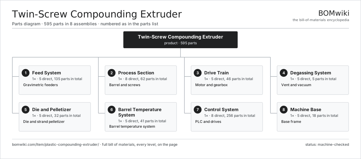
| # | Part | Qty | What it does |
|---|---|---|---|
| 1 | Feed System 5 parts | 1× | Gravimetric feeders |
| 2 | Process Section 8 parts | 1× | Barrel and screws |
| 3 | Drive Train 5 parts | 1× | Motor and gearbox |
| 4 | Degassing System 5 parts | 1× | Vent and vacuum |
| 5 | Die and Pelletizer 5 parts | 1× | Die and strand pelletizer |
| 6 | Barrel Temperature System 5 parts | 1× | Barrel temperature system |
| 7 | Control System 8 parts | 1× | PLC and drives |
| 8 | Machine Base 5 parts | 1× | Base frame |
3D model
No 3D model yet. Have a CAD file of this? Add a 3D model — STL renders right on this page; STEP, FreeCAD, and OpenSCAD sources are welcome too (openly licensed, like all 3D models on BOMwiki).
Build & assembly graph
expand / collapse · shared sub-assemblies converge · links to related products · est. labourTap an assembly to expand/collapse · tap a part to open it · use “Open page” for any node · drag to pan, scroll to zoom.
Bill of materials for Twin-Screw Compounding Extruder
8 top-level lines · 89 rows shown · 595 parts total · indented to 3 levels| # | Item / sub-assembly | Part no. | Qty/assy | Ext. qty | Parts | Type |
|---|---|---|---|---|---|---|
| 1 | Feed System 5 parts | pce-feed-system | 1× | 1 | 135 | assembly |
| 1.1 | Main Feeder 4 parts | pce-main-feeder | 1× | 1 | 28 | assembly |
| 1.1.1 | Feed Screw | pce-feed-screw | 2× | 2 | · | part |
| 1.1.2 | Load Cell | pce-load-cell | 1× | 1 | · | part |
| 1.1.3 | Servo Motor 4 parts + deeper › | servo-motor | 1× | 1 | 24 | assembly |
| 1.1.4 | Hopper Agitator | pce-agitator | 1× | 1 | · | part |
| 1.2 | Additive Feeder 3 parts | pce-additive-feeder | 3× | 3 | 26 | assembly |
| 1.2.1 | Feed Screw | pce-feed-screw | 1× | 3 | · | part |
| 1.2.2 | Load Cell | pce-load-cell | 1× | 3 | · | part |
| 1.2.3 | Servo Motor 4 parts + deeper › | servo-motor | 1× | 3 | 24 | assembly |
| 1.3 | Liquid Injector | pce-liquid-injector | 1× | 1 | · | part |
| 1.4 | Side Feeder 3 parts | pce-side-feeder | 1× | 1 | 27 | assembly |
| 1.4.1 | Side Feeder Screw | pce-sf-screw | 2× | 2 | · | part |
| 1.4.2 | Side Feeder Barrel | pce-sf-barrel | 1× | 1 | · | part |
| 1.4.3 | Servo Motor 4 parts + deeper › | servo-motor | 1× | 1 | 24 | assembly |
| 1.5 | Feed Hopper | pce-feed-hopper | 1× | 1 | · | part |
| 2 | Process Section 8 parts | pce-process-section | 1× | 1 | 62 | assembly |
| 2.1 | Barrel Segment | pce-barrel-segment | 8× | 8 | · | part |
| 2.2 | Barrel Liner | pce-barrel-liner | 8× | 8 | · | part |
| 2.3 | Screw Shaft | pce-screw-shaft | 2× | 2 | · | part |
| 2.4 | Conveying Element | pce-conveying-element | 24× | 24 | · | part |
| 2.5 | Kneading Block | pce-kneading-block | 12× | 12 | · | part |
| 2.6 | Mixing Element | pce-mixing-element | 6× | 6 | · | part |
| 2.7 | Feed Port | pce-feed-port | 1× | 1 | · | part |
| 2.8 | Fastener Set | fastener-set | 1× | 1 | · | part |
| 3 | Drive Train 5 parts | pce-drive-train | 1× | 1 | 46 | assembly |
| 3.1 | AC Drive Motor 5 parts | pce-drive-motor | 1× | 1 | 26 | assembly |
| 3.1.1 | Stator Assembly 3 parts + deeper › | stator-assembly | 1× | 1 | 3 | assembly |
| 3.1.2 | Rotor Assembly 4 parts + deeper › | rotor-assembly | 1× | 1 | 19 | assembly |
| 3.1.3 | Motor Housing | motor-housing | 1× | 1 | · | part |
| 3.1.4 | Ball Bearing | ball-bearing | 2× | 2 | · | part |
| 3.1.5 | Encoder | encoder | 1× | 1 | · | part |
| 3.2 | Distribution Gearbox 4 parts | pce-distribution-gearbox | 1× | 1 | 17 | assembly |
| 3.2.1 | Helical Gear Pair | gear-pair | 4× | 4 | · | part |
| 3.2.2 | Gearbox Housing | gearbox-housing | 1× | 1 | · | part |
| 3.2.3 | Ball Bearing | ball-bearing | 8× | 8 | · | part |
| 3.2.4 | Oil Seal | oil-seal | 4× | 4 | · | part |
| 3.3 | Safety Coupling | pce-coupling | 1× | 1 | · | part |
| 3.4 | Thrust Bearing Block | pce-thrust-bearing | 1× | 1 | · | part |
| 3.5 | Lube Unit | pce-lube-unit | 1× | 1 | · | part |
| 4 | Degassing System 5 parts | pce-degassing-system | 1× | 1 | 5 | assembly |
| 4.1 | Atmospheric Vent | pce-atmos-vent | 1× | 1 | · | part |
| 4.2 | Vacuum Vent | pce-vacuum-vent | 1× | 1 | · | part |
| 4.3 | Vacuum Pump | pce-vacuum-pump | 1× | 1 | · | part |
| 4.4 | Vent Stuffer | pce-vent-stuffer | 1× | 1 | · | part |
| 4.5 | Condenser | pce-condenser | 1× | 1 | · | part |
| 5 | Die and Pelletizer 5 parts | pce-die-pelletizer | 1× | 1 | 32 | assembly |
| 5.1 | Strand Die | pce-strand-die | 1× | 1 | · | part |
| 5.2 | Water Bath | pce-water-bath | 1× | 1 | · | part |
| 5.3 | Air Knife | pce-air-knife | 1× | 1 | · | part |
| 5.4 | Strand Pelletizer 4 parts | pce-strand-pelletizer | 1× | 1 | 28 | assembly |
| 5.4.1 | Feed Roll | pce-feed-roll | 2× | 2 | · | part |
| 5.4.2 | Rotor Knife | pce-rotor-knife | 1× | 1 | · | part |
| 5.4.3 | Bed Knife | pce-bed-knife | 1× | 1 | · | part |
| 5.4.4 | Servo Motor 4 parts + deeper › | servo-motor | 1× | 1 | 24 | assembly |
| 5.5 | Classifier Screen | pce-vibrating-screen | 1× | 1 | · | part |
| 6 | Barrel Temperature System 5 parts | pce-heating-cooling | 1× | 1 | 41 | assembly |
| 6.1 | Cartridge Heater | pce-cartridge-heater | 16× | 16 | · | part |
| 6.2 | Cooling Bore | pce-cooling-bore | 8× | 8 | · | part |
| 6.3 | Thermocouple | pce-thermocouple | 8× | 8 | · | part |
| 6.4 | Water Manifold | pce-water-manifold | 1× | 1 | · | part |
| 6.5 | Solenoid Valve | pce-solenoid-valve | 8× | 8 | · | part |
| 7 | Control System 8 parts | pce-control-system | 1× | 1 | 256 | assembly |
| 7.1 | PLC 4 parts | pce-plc | 1× | 1 | 188 | assembly |
| 7.1.1 | Bare PCB | pcb-bare | 1× | 1 | · | part |
| 7.1.2 | Microcontroller | mcu | 1× | 1 | · | part |
| 7.1.3 | I/O Module | io-module | 6× | 6 | · | part |
| 7.1.4 | SMD Passive (R/C/L) | smd-passives | 180× | 180 | · | part |
| 7.2 | Variable Frequency Drive 4 parts | pce-vfd | 4× | 4 | 5 | assembly |
| 7.2.1 | Bare PCB | pcb-bare | 1× | 4 | · | part |
| 7.2.2 | IGBT Power Module | igbt-module | 1× | 4 | · | part |
| 7.2.3 | DC-Link Capacitor | dc-link-cap | 2× | 8 | · | part |
| 7.2.4 | Microcontroller | mcu | 1× | 4 | · | part |
| 7.3 | HMI Panel 4 parts | pce-hmi | 1× | 1 | 4 | assembly |
| 7.3.1 | LCD Panel | lcd-panel | 1× | 1 | · | part |
| 7.3.2 | Touch Digitizer | touch-digitizer | 1× | 1 | · | part |
| 7.3.3 | Bare PCB | pcb-bare | 1× | 1 | · | part |
| 7.3.4 | Microcontroller | mcu | 1× | 1 | · | part |
| 7.4 | Temperature Controller | pce-temp-controller | 1× | 1 | · | part |
| 7.5 | Torque Monitor | pce-torque-monitor | 1× | 1 | · | part |
| 7.6 | Power Supply | power-supply | 1× | 1 | · | part |
| 7.7 | Wire Bundle | wire-bundle | 1× | 1 | · | part |
| 7.8 | Connector | connector | 40× | 40 | · | part |
| 8 | Machine Base 5 parts | pce-machine-base | 1× | 1 | 18 | assembly |
| 8.1 | Base Weldment | pce-base-weldment | 1× | 1 | · | part |
| 8.2 | Barrel Support | pce-barrel-support | 4× | 4 | · | part |
| 8.3 | Sheet Metal Panel | sheet-panel | 6× | 6 | · | part |
| 8.4 | Leveling Foot | pce-leveling-foot | 6× | 6 | · | part |
| 8.5 | Fastener Set | fastener-set | 1× | 1 | · | part |
Sourcing: possible vendors
Prices, MOQ, and lead times are algorithmic estimates, not quotes, and not claims about these companies. Company mappings are curated by keyword; est. price band $5k–$2M. How estimates work| Vendor | HQ | Specialty | MOQ | Lead time |
|---|---|---|---|---|
| atlascopco.com ↗ | Stockholm, SE | Compressors & industrial | 10 units | 12–20 wks |
|
🇦🇹Andritz
andritz.com ↗
|
Graz, AT | Process plants & machinery | 10 units | 12–20 wks |
| buhlergroup.com ↗ | Uzwil, CH | Food & materials processing | 10 units | 12–20 wks |
| gea.com ↗ | Düsseldorf, DE | Process technology | 10 units | 12–20 wks |
| mhi.com ↗ | Tokyo, JP | Heavy machinery | 10 units | 12–20 wks |
943-word article