Blown Film Extrusion Line
ProductOverview
A blown film line makes thin plastic film by extruding molten polymer through a ring-shaped die, then inflating the resulting tube like a long balloon while it cools. The tube, called the bubble, is drawn upward several metres, frozen solid by a curtain of air, then folded flat and wound into rolls. It is the dominant way to make the polyethylene film used for bags, agricultural cover, shrink wrap, liners, and lamination stock, because one machine can make a wide range of widths and gauges simply by changing the inflation and draw settings rather than the hardware.
The line is a vertical process. The Single-Screw Extruder melts the resin and pushes it up the Adapter Pipe into the Blown Film Die, which forms the melt into a thin tube. The Air Ring, fed by the Air System, cools the tube and sets the height at which it freezes. The Bubble Cage steadies the soft bubble, the Collapsing and Haul-Off flattens and pulls it, and the Surface Winder turns the flat web into finished rolls. The Control System holds every speed and temperature, and the whole stack is carried by the Tower and Frame.
Melting and metering
The Single-Screw Extruder is a single-screw machine. Pellets drop from the Feed Hopper through a water-cooled Feed Throat onto the Extruder Screw, a barrier-flighted screw turning inside a nitrided Extruder Barrel. The screw has a feed zone that conveys solid pellets, a compression zone where Band Heater bands and the shear of the flights melt the resin, and a metering zone that builds the pressure needed at the die. Each Thermocouple reports its zone temperature, and a Barrel Cooling Fan fan trims any zone that runs hot from shear. The AC Drive Motor turns the screw through a Reduction Gearbox, and a Thrust Bearing Block block carries the back-thrust of melt pressure. Before the melt leaves the extruder it passes the Screen Changer, where wire Filter Screen layers backed by a Breaker Plate strain out gels, and a Melt Pump smooths the pressure so the film gauge does not pulse.
Forming the bubble
The Blown Film Die turns the round melt stream into a thin tube. Inside the Die Body, a grooved Spiral Mandrel wraps the melt into overlapping spiral layers so the finished tube has no weld lines, and the melt finally exits through the Die Lips, an annular gap of roughly 0.8 to 2 mm that sets the starting wall thickness. The Centering Bolt centering screws and the Die Heater bands keep the wall even and the steel at melt temperature. The molten tube leaves the lips moving slowly, and two things stretch it into film: internal air inflates it sideways to the blow-up ratio, and the haul-off draws it upward to thin the wall. A bubble blown to 2.5 times the die diameter and drawn at a high ratio can turn a 1 mm melt wall into a 30 micron film.
Cooling and stabilizing
The film must freeze before it can be handled, and how fast it freezes sets the line speed. The Air Ring surrounds the base of the bubble and blows a high-velocity sheet of air from its Air Lip slots, set so the Cooling Blower feeds even flow all around. The point where the film turns from clear melt to hazy solid is the frost line, and holding it steady is the heart of running the line. Modern lines add internal bubble cooling: the IBC Blower and its IBC Valve units exchange the warm air trapped inside the bubble, while Bubble Width Sensor units measure the bubble diameter and feed a loop that holds a constant layflat width without an operator touching it. An Air Chiller can drop the air temperature to push speed higher. Above the air ring the Bubble Cage surrounds the still-soft tube with rings of Cage Roller rollers on telescoping Cage Arm arms, keeping it centered and round as it rises.
Collapsing, treating, and winding
Once frozen, the round bubble must become a flat web. The Collapsing Frame guides it between converging boards of low-friction Collapse Slat slats that fold it gently into two layers, and the Nip Roll pair at the top seals the bubble and pulls the film at the speed the Haul-Off Motor commands. Because the die always leaves slightly thick and thin bands, the Turning Bar units or an oscillating haul-off rotate the web so those bands spread around the roll instead of stacking into a hard ridge. Film meant for printing or lamination passes the Corona Treater, where a Corona Electrode discharge over the Corona Roll raises the surface energy so inks and adhesives bond. The web then runs to the Surface Winder, where a Slitter Bank bank of Razor Blade blades trims and divides it, and torque-driven Winder Spindle shafts wind it onto cores at a tension held by the Dancer Roll.
Control and structure
The Control System ties the line together. A PLC runs the gauge, tension, and temperature loops; a Variable Frequency Drive sets each motor speed; and the Temperature Controller drives the heater zones. A traversing Gauge Scanner maps film thickness across the web and feeds corrections back to the die and the IBC so the profile stays flat. The operator works from the HMI Panel touchscreen, calling up resin recipes and watching the frost line and gauge map. All of this sits on the Tower and Frame, whose Tower Column columns and Access Platform walkways carry the cage and collapsing frame at the height the film needs to cool, often eight metres or more above the floor.
Materials, variants, and use
The line runs mostly polyethylene, from soft LDPE for stretch and produce bags to tough LLDPE and stiff HDPE for liners and merchandise bags, often as a blend. Single-layer lines make commodity film; three-layer lines feed three extruders into one die so a barrier or slip layer can be sandwiched between skins for food packaging. Output ranges from under 100 kg/h on a narrow line to several hundred kg/h on a wide one, and the same machine can swing from a clear 15 micron bread bag film to a 200 micron construction sheet by changing the blow-up ratio, draw, and cooling. Compared with the Cast Film Extrusion Line, which cools melt on a chilled roll, blown film cools in air, which makes tougher, more balanced film and easy width changes, at the cost of slower cooling and slightly less optical clarity.
Blown Film Extrusion Line parts and their functions
9 top-level parts · 436 parts in total · full bill of materials below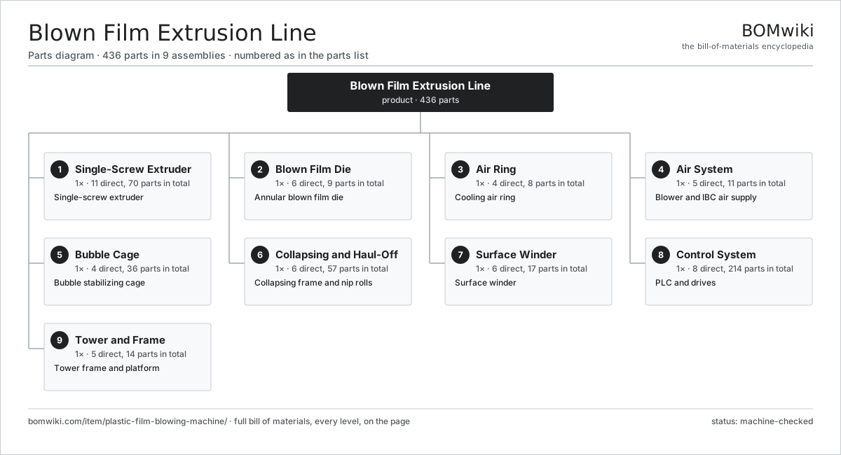
| # | Part | Qty | What it does |
|---|---|---|---|
| 1 | Single-Screw Extruder 11 parts | 1× | Single-screw extruder |
| 2 | Blown Film Die 6 parts | 1× | Annular blown film die |
| 3 | Air Ring 4 parts | 1× | Cooling air ring |
| 4 | Air System 5 parts | 1× | Blower and IBC air supply |
| 5 | Bubble Cage 4 parts | 1× | Bubble stabilizing cage |
| 6 | Collapsing and Haul-Off 6 parts | 1× | Collapsing frame and nip rolls |
| 7 | Surface Winder 6 parts | 1× | Surface winder |
| 8 | Control System 8 parts | 1× | PLC and drives |
| 9 | Tower and Frame 5 parts | 1× | Tower frame and platform |
3D model
No 3D model yet. Have a CAD file of this? Add a 3D model — STL renders right on this page; STEP, FreeCAD, and OpenSCAD sources are welcome too (openly licensed, like all 3D models on BOMwiki).
Build & assembly graph
expand / collapse · shared sub-assemblies converge · links to related products · est. labourTap an assembly to expand/collapse · tap a part to open it · use “Open page” for any node · drag to pan, scroll to zoom.
Bill of materials for Blown Film Extrusion Line
9 top-level lines · 108 rows shown · 436 parts total · indented to 3 levels| # | Item / sub-assembly | Part no. | Qty/assy | Ext. qty | Parts | Type |
|---|---|---|---|---|---|---|
| 1 | Single-Screw Extruder 11 parts | pfbm-extruder | 1× | 1 | 70 | assembly |
| 1.1 | Feed Hopper 4 parts | pfbm-feed-hopper | 1× | 1 | 4 | assembly |
| 1.1.1 | Hopper Cone | pfbm-hopper-cone | 1× | 1 | · | part |
| 1.1.2 | Feed Throat | pfbm-feed-throat | 1× | 1 | · | part |
| 1.1.3 | Hopper Magnet | pfbm-hopper-magnet | 1× | 1 | · | part |
| 1.1.4 | Slide Gate | pfbm-slide-gate | 1× | 1 | · | part |
| 1.2 | Extruder Barrel | pfbm-barrel | 1× | 1 | · | part |
| 1.3 | Extruder Screw | pfbm-screw | 1× | 1 | · | part |
| 1.4 | Band Heater | pfbm-barrel-heater | 6× | 6 | · | part |
| 1.5 | Barrel Cooling Fan | pfbm-barrel-cooling | 4× | 4 | · | part |
| 1.6 | Thermocouple | pfbm-thermocouple | 6× | 6 | · | part |
| 1.7 | Reduction Gearbox 5 parts | pfbm-gearbox | 1× | 1 | 10 | assembly |
| 1.7.1 | Helical Gear Pair | gear-pair | 2× | 2 | · | part |
| 1.7.2 | Gearbox Housing | gearbox-housing | 1× | 1 | · | part |
| 1.7.3 | Ball Bearing | ball-bearing | 4× | 4 | · | part |
| 1.7.4 | Oil Seal | oil-seal | 2× | 2 | · | part |
| 1.7.5 | Lube Oil Pump | pfbm-oil-pump | 1× | 1 | · | part |
| 1.8 | AC Drive Motor 5 parts | pfbm-drive-motor | 1× | 1 | 26 | assembly |
| 1.8.1 | Stator Assembly 3 parts + deeper › | stator-assembly | 1× | 1 | 3 | assembly |
| 1.8.2 | Rotor Assembly 4 parts + deeper › | rotor-assembly | 1× | 1 | 19 | assembly |
| 1.8.3 | Motor Housing | motor-housing | 1× | 1 | · | part |
| 1.8.4 | Ball Bearing | ball-bearing | 2× | 2 | · | part |
| 1.8.5 | Encoder | encoder | 1× | 1 | · | part |
| 1.9 | Thrust Bearing Block | pfbm-thrust-bearing | 1× | 1 | · | part |
| 1.10 | Screen Changer 3 parts | pfbm-screen-changer | 1× | 1 | 5 | assembly |
| 1.10.1 | Breaker Plate | pfbm-breaker-plate | 1× | 1 | · | part |
| 1.10.2 | Filter Screen | pfbm-filter-screen | 3× | 3 | · | part |
| 1.10.3 | Changer Piston | pfbm-changer-piston | 1× | 1 | · | part |
| 1.11 | Melt Pump 4 parts | pfbm-melt-pump | 1× | 1 | 6 | assembly |
| 1.11.1 | Helical Gear Pair | gear-pair | 1× | 1 | · | part |
| 1.11.2 | Gearbox Housing | gearbox-housing | 1× | 1 | · | part |
| 1.11.3 | Ball Bearing | ball-bearing | 2× | 2 | · | part |
| 1.11.4 | Oil Seal | oil-seal | 2× | 2 | · | part |
| 2 | Blown Film Die 6 parts | pfbm-die-head | 1× | 1 | 9 | assembly |
| 2.1 | Die Body | pfbm-die-body | 1× | 1 | · | part |
| 2.2 | Spiral Mandrel | pfbm-die-mandrel | 1× | 1 | · | part |
| 2.3 | Die Lips | pfbm-die-lips | 1× | 1 | · | part |
| 2.4 | Die Heater | pfbm-die-heater | 4× | 4 | · | part |
| 2.5 | Centering Bolt | pfbm-die-bolt | 1× | 1 | · | part |
| 2.6 | Adapter Pipe | pfbm-adapter-pipe | 1× | 1 | · | part |
| 3 | Air Ring 4 parts | pfbm-air-ring | 1× | 1 | 8 | assembly |
| 3.1 | Air Ring Body | pfbm-air-ring-body | 1× | 1 | · | part |
| 3.2 | Air Lip | pfbm-air-ring-lip | 2× | 2 | · | part |
| 3.3 | Air Plenum | pfbm-air-plenum | 1× | 1 | · | part |
| 3.4 | Air Hose | pfbm-air-hose | 4× | 4 | · | part |
| 4 | Air System 5 parts | pfbm-air-system | 1× | 1 | 11 | assembly |
| 4.1 | Cooling Blower 4 parts | pfbm-cooling-blower | 1× | 1 | 5 | assembly |
| 4.1.1 | Blower Impeller | pfbm-blower-impeller | 1× | 1 | · | part |
| 4.1.2 | Blower Housing | pfbm-blower-housing | 1× | 1 | · | part |
| 4.1.3 | Blower Motor | pfbm-blower-motor | 1× | 1 | · | part |
| 4.1.4 | Ball Bearing | ball-bearing | 2× | 2 | · | part |
| 4.2 | IBC Blower | pfbm-ibc-blower | 1× | 1 | · | part |
| 4.3 | IBC Valve | pfbm-ibc-valve | 2× | 2 | · | part |
| 4.4 | Air Chiller | pfbm-air-chiller | 1× | 1 | · | part |
| 4.5 | Bubble Width Sensor | pfbm-ultrasonic-sensor | 2× | 2 | · | part |
| 5 | Bubble Cage 4 parts | pfbm-bubble-cage | 1× | 1 | 36 | assembly |
| 5.1 | Cage Ring | pfbm-cage-ring | 3× | 3 | · | part |
| 5.2 | Cage Roller | pfbm-cage-roller | 24× | 24 | · | part |
| 5.3 | Cage Arm | pfbm-cage-arm | 8× | 8 | · | part |
| 5.4 | Fastener Set | fastener-set | 1× | 1 | · | part |
| 6 | Collapsing and Haul-Off 6 parts | pfbm-nip-haul-off | 1× | 1 | 57 | assembly |
| 6.1 | Collapsing Frame 2 parts | pfbm-collapsing-frame | 1× | 1 | 42 | assembly |
| 6.1.1 | Collapse Slat | pfbm-collapse-slat | 40× | 40 | · | part |
| 6.1.2 | Frame Side Panel | pfbm-frame-side | 2× | 2 | · | part |
| 6.2 | Nip Roll | pfbm-nip-roll | 2× | 2 | · | part |
| 6.3 | Haul-Off Motor | pfbm-haul-off-motor | 1× | 1 | · | part |
| 6.4 | Turning Bar | pfbm-turning-bar | 2× | 2 | · | part |
| 6.5 | Corona Treater 3 parts | pfbm-corona-treater | 1× | 1 | 4 | assembly |
| 6.5.1 | Corona Electrode | pfbm-corona-electrode | 2× | 2 | · | part |
| 6.5.2 | Corona Roll | pfbm-corona-roll | 1× | 1 | · | part |
| 6.5.3 | Power Supply | power-supply | 1× | 1 | · | part |
| 6.6 | Idler Roll | pfbm-idler-roll | 6× | 6 | · | part |
| 7 | Surface Winder 6 parts | pfbm-winder | 1× | 1 | 17 | assembly |
| 7.1 | Winder Spindle | pfbm-winder-spindle | 2× | 2 | · | part |
| 7.2 | Winder Motor | pfbm-winder-motor | 2× | 2 | · | part |
| 7.3 | Dancer Roll | pfbm-dancer-roll | 1× | 1 | · | part |
| 7.4 | Slitter Bank 2 parts | pfbm-slitter | 1× | 1 | 7 | assembly |
| 7.4.1 | Razor Blade | pfbm-razor-blade | 6× | 6 | · | part |
| 7.4.2 | Slitter Bar | pfbm-slitter-bar | 1× | 1 | · | part |
| 7.5 | Core Chuck | pfbm-core-chuck | 4× | 4 | · | part |
| 7.6 | Cutoff Blade | pfbm-cutoff-blade | 1× | 1 | · | part |
| 8 | Control System 8 parts | pfbm-control-system | 1× | 1 | 214 | assembly |
| 8.1 | PLC 4 parts | pfbm-plc | 1× | 1 | 156 | assembly |
| 8.1.1 | Bare PCB | pcb-bare | 1× | 1 | · | part |
| 8.1.2 | Microcontroller | mcu | 1× | 1 | · | part |
| 8.1.3 | I/O Module | io-module | 4× | 4 | · | part |
| 8.1.4 | SMD Passive (R/C/L) | smd-passives | 150× | 150 | · | part |
| 8.2 | Variable Frequency Drive 4 parts | pfbm-vfd | 4× | 4 | 5 | assembly |
| 8.2.1 | Bare PCB | pcb-bare | 1× | 4 | · | part |
| 8.2.2 | IGBT Power Module | igbt-module | 1× | 4 | · | part |
| 8.2.3 | DC-Link Capacitor | dc-link-cap | 2× | 8 | · | part |
| 8.2.4 | Microcontroller | mcu | 1× | 4 | · | part |
| 8.3 | HMI Panel 4 parts | pfbm-hmi | 1× | 1 | 4 | assembly |
| 8.3.1 | LCD Panel | lcd-panel | 1× | 1 | · | part |
| 8.3.2 | Touch Digitizer | touch-digitizer | 1× | 1 | · | part |
| 8.3.3 | Bare PCB | pcb-bare | 1× | 1 | · | part |
| 8.3.4 | Microcontroller | mcu | 1× | 1 | · | part |
| 8.4 | Temperature Controller | pfbm-temp-controller | 1× | 1 | · | part |
| 8.5 | Gauge Scanner | pfbm-gauge-scanner | 1× | 1 | · | part |
| 8.6 | Power Supply | power-supply | 1× | 1 | · | part |
| 8.7 | Wire Bundle | wire-bundle | 1× | 1 | · | part |
| 8.8 | Connector | connector | 30× | 30 | · | part |
| 9 | Tower and Frame 5 parts | pfbm-frame-tower | 1× | 1 | 14 | assembly |
| 9.1 | Tower Column | pfbm-tower-column | 4× | 4 | · | part |
| 9.2 | Access Platform | pfbm-platform | 2× | 2 | · | part |
| 9.3 | Oscillating Platform | pfbm-oscillating-platform | 1× | 1 | · | part |
| 9.4 | Sheet Metal Panel | sheet-panel | 6× | 6 | · | part |
| 9.5 | Fastener Set | fastener-set | 1× | 1 | · | part |
Related products
same domain, ranked by shared parts Twin-Screw Compounding Extruder
595 parts · shares 25 with this page
WPC Profile Extrusion Line
422 parts · shares 24 with this page
Underwater Pelletizing System
290 parts · shares 23 with this page
Coil Coating Line
1,767 parts · shares 22 with this page
Acid Pickling Line
1,163 parts · shares 21 with this page
Twin-Screw Compounding Extruder
595 parts · shares 25 with this page
WPC Profile Extrusion Line
422 parts · shares 24 with this page
Underwater Pelletizing System
290 parts · shares 23 with this page
Coil Coating Line
1,767 parts · shares 22 with this page
Acid Pickling Line
1,163 parts · shares 21 with this page
Sourcing: possible vendors
Prices, MOQ, and lead times are algorithmic estimates, not quotes, and not claims about these companies. Company mappings are curated by keyword; est. price band $5k–$2M. How estimates work| Vendor | HQ | Specialty | MOQ | Lead time |
|---|---|---|---|---|
| atlascopco.com ↗ | Stockholm, SE | Compressors & industrial | 10 units | 12–20 wks |
|
🇦🇹Andritz
andritz.com ↗
|
Graz, AT | Process plants & machinery | 10 units | 12–20 wks |
| buhlergroup.com ↗ | Uzwil, CH | Food & materials processing | 10 units | 12–20 wks |
| gea.com ↗ | Düsseldorf, DE | Process technology | 10 units | 12–20 wks |
| mhi.com ↗ | Tokyo, JP | Heavy machinery | 10 units | 12–20 wks |
1,142-word article