Reaction Injection Molding Machine
ProductOverview
A reaction injection molding machine forms large plastic parts by mixing two reactive liquids, a polyol and an isocyanate, and injecting the blend into a mold where they polymerize into polyurethane. The reaction happens inside the mold rather than before it, so the machine handles thin watery liquids at low pressure rather than a thick melt at high pressure. That lets the Reaction Injection Molding Machine fill very large molds, automotive bumpers, body panels, instrument-panel skins, foamed structural parts and equipment enclosures, with modest clamp force.
RIM differs from thermoplastic injection in three ways: the materials are liquid and react chemically, mixing is done by colliding jets rather than a screw, and the Impingement Mix Head cleans itself mechanically so no solvent is needed. The viscosity of the components is close to that of oil, so the hardest engineering problems are accurate metering, exact ratio, and keeping the two streams apart until the instant they mix.
Component storage and conditioning
Each component lives in a Component Day Tank. The Day Tank Vessel is stainless steel under a Nitrogen Blanket Regulator, because isocyanate reacts with atmospheric moisture and would skin over or form solids. Many polyols carry mineral or glass filler, so a slow Tank Agitator keeps the contents homogeneous and the filler in suspension. A Tank Jacket and the Recirculation Pump hold the material near 30 C, and a Level Transmitter tracks inventory.
Before the component reaches the metering pumps it passes through the Temperature Conditioning Unit unit. Polyurethane viscosity and reaction speed are strongly temperature dependent, so each line has a Heater-Chiller Unit holding it within 1 degree, circulated by a Conditioning Pump through a Plate Heat Exchanger and verified by an RTD Temperature Probe. Stable temperature is what makes shot-to-shot quality repeatable.
Metering and ratio control
The heart of accuracy is the High-Pressure Metering Unit. Two Metering Pump units, axial piston pumps each driven by a Metering Servo Motor, deliver polyol and isocyanate at 150-250 bar. A Coriolis Flow Meter of the Coriolis type measures the real mass flow of each line, and the Ratio Controller trims pump speed in a closed loop so the polyol to isocyanate ratio stays within 1 percent. An off-ratio shot produces a part that is soft, brittle, or chemically unfinished, so ratio is monitored on every cycle, not just at setup. Between shots, Recirculation Valve units return both components to their tanks so the lines stay primed and at temperature.
Impingement mixing
The two high-pressure streams meet in the Impingement Mix Head. Inside the Mixing Chamber, each component passes through a calibrated Injector Nozzle that forms a fine high-velocity jet. The jets collide head-on, and the energy of that impingement mixes them thoroughly in milliseconds with no mechanical agitator and no solvent. This is why RIM is called high-pressure mixing even though the cavity pressure is low.
The clever part is self-cleaning. As soon as the shot ends, the Mix Head Cylinder drives the Clean-Out Piston forward through the chamber, sweeping out the last reacting material before it can cure and clog the head. During the wait between shots the Mix Head Recycle Valve units route both components back to recirculation. Older RIM machines flushed the head with solvent after every shot; the self-cleaning head eliminated that waste and the associated emissions.
Mold carrier and tilting
The mixed liquid is injected into a mold held in the Tilting Mold Carrier. Because RIM parts are large and the cavity pressure is low, the carrier needs far less clamp force than a thermoplastic press of the same shot size. Two Carrier Clamp Cylinder units press the Carrier Platen halves together along the Guide Column columns, and Mold Quick Clamp units secure each mold half.
A Tilt Mechanism tips the whole carrier during filling. Tilting lets the liquid flow into the cavity by gravity and lets air escape ahead of the rising fill front, which is critical for foamed parts where trapped air becomes a void. After cure the carrier tilts again to present the part for demolding. The reaction is exothermic, and for foamed parts the gas from the blowing agent also expands the material to fill the cavity.
Hydraulics, control and frame
A Hydraulic Power Unit supplies oil to the mix head piston, the clamp cylinders and the tilt drive. The Control System coordinates the whole sequence: a Process PLC runs ratio control, shot timing, temperature setpoints and clamp interlocks, two Servo Drive units close the loop on the metering servos, and the operator manages recipes from the HMI Touch Panel touchscreen. The Machine Frame and Guarding carries everything, with a Spill Containment Tray to contain any isocyanate or polyol leak and interlocked Guard Panel guarding around the mix head.
Variants
Structural RIM (SRIM) places a glass fiber preform in the mold before injection, so the polyurethane impregnates the reinforcement and yields a stiff composite panel. Reinforced RIM (RRIM) blends milled glass into the polyol for added stiffness without a preform. Foam RIM adds a blowing agent to make low-density parts such as steering wheels, armrests and refrigerator insulation. Larger machines run multiple mix heads from a single metering unit to fill very large or multi-gated molds, and self-skinning grades produce a dense surface over a foam core in a single shot.
Reaction Injection Molding Machine parts and their functions
8 top-level parts · 457 parts in total · full bill of materials below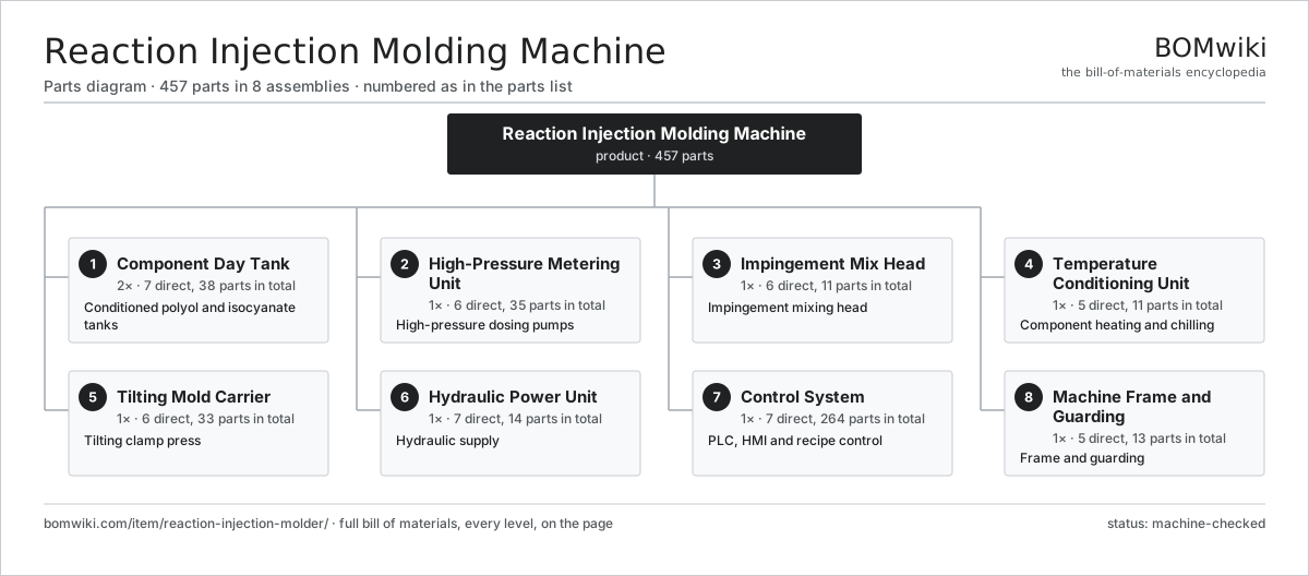
| # | Part | Qty | What it does |
|---|---|---|---|
| 1 | Component Day Tank 7 parts | 2× | Conditioned polyol and isocyanate tanks |
| 2 | High-Pressure Metering Unit 6 parts | 1× | High-pressure dosing pumps |
| 3 | Impingement Mix Head 6 parts | 1× | Impingement mixing head |
| 4 | Temperature Conditioning Unit 5 parts | 1× | Component heating and chilling |
| 5 | Tilting Mold Carrier 6 parts | 1× | Tilting clamp press |
| 6 | Hydraulic Power Unit 7 parts | 1× | Hydraulic supply |
| 7 | Control System 7 parts | 1× | PLC, HMI and recipe control |
| 8 | Machine Frame and Guarding 5 parts | 1× | Frame and guarding |
3D model
No 3D model yet. Have a CAD file of this? Add a 3D model — STL renders right on this page; STEP, FreeCAD, and OpenSCAD sources are welcome too (openly licensed, like all 3D models on BOMwiki).
Build & assembly graph
expand / collapse · shared sub-assemblies converge · links to related products · est. labourTap an assembly to expand/collapse · tap a part to open it · use “Open page” for any node · drag to pan, scroll to zoom.
Bill of materials for Reaction Injection Molding Machine
8 top-level lines · 83 rows shown · 457 parts total · indented to 3 levels| # | Item / sub-assembly | Part no. | Qty/assy | Ext. qty | Parts | Type |
|---|---|---|---|---|---|---|
| 1 | Component Day Tank 7 parts | rim-day-tank-station | 2× | 2 | 38 | assembly |
| 1.1 | Day Tank Vessel | rim-tank-vessel | 1× | 2 | · | part |
| 1.2 | Tank Agitator 6 parts | rim-tank-agitator | 1× | 2 | 30 | assembly |
| 1.2.1 | Servo Motor 4 parts + deeper › | servo-motor | 1× | 2 | 24 | assembly |
| 1.2.2 | Gearbox Housing | gearbox-housing | 1× | 2 | · | part |
| 1.2.3 | Helical Gear Pair | gear-pair | 1× | 2 | · | part |
| 1.2.4 | Agitator Blade | rim-agitator-blade | 1× | 2 | · | part |
| 1.2.5 | Ball Bearing | ball-bearing | 2× | 4 | · | part |
| 1.2.6 | Oil Seal | oil-seal | 1× | 2 | · | part |
| 1.3 | Tank Jacket | rim-tank-jacket | 1× | 2 | · | part |
| 1.4 | Nitrogen Blanket Regulator | rim-nitrogen-blanket | 1× | 2 | · | part |
| 1.5 | Level Transmitter | rim-level-sensor | 1× | 2 | · | part |
| 1.6 | Recirculation Pump | rim-tank-recirc-pump | 1× | 2 | · | part |
| 1.7 | O-Ring Set | oring-set | 3× | 6 | · | part |
| 2 | High-Pressure Metering Unit 6 parts | rim-metering-unit | 1× | 1 | 35 | assembly |
| 2.1 | Metering Pump 5 parts | rim-metering-pump | 2× | 2 | 13 | assembly |
| 2.1.1 | Pump Cylinder Block | rim-pump-cylinder-block | 1× | 2 | · | part |
| 2.1.2 | Pump Piston | rim-pump-piston | 7× | 14 | · | part |
| 2.1.3 | Swash Plate | rim-swash-plate | 1× | 2 | · | part |
| 2.1.4 | Ball Bearing | ball-bearing | 2× | 4 | · | part |
| 2.1.5 | Oil Seal | oil-seal | 2× | 4 | · | part |
| 2.2 | Metering Servo Motor | rim-metering-servo | 2× | 2 | · | part |
| 2.3 | Coriolis Flow Meter | rim-flow-meter | 2× | 2 | · | part |
| 2.4 | Ratio Controller | rim-ratio-controller | 1× | 1 | · | part |
| 2.5 | Recirculation Valve | rim-recirc-valve | 2× | 2 | · | part |
| 2.6 | Pressure Sensor | pressure-sensor | 2× | 2 | · | part |
| 3 | Impingement Mix Head 6 parts | rim-mix-head | 1× | 1 | 11 | assembly |
| 3.1 | Mixing Chamber | rim-mix-chamber | 1× | 1 | · | part |
| 3.2 | Clean-Out Piston | rim-control-piston | 1× | 1 | · | part |
| 3.3 | Injector Nozzle | rim-nozzle-insert | 2× | 2 | · | part |
| 3.4 | Mix Head Cylinder | rim-mix-head-cylinder | 1× | 1 | · | part |
| 3.5 | Mix Head Recycle Valve | rim-mix-head-valve | 2× | 2 | · | part |
| 3.6 | O-Ring Set | oring-set | 4× | 4 | · | part |
| 4 | Temperature Conditioning Unit 5 parts | rim-temperature-conditioning | 1× | 1 | 11 | assembly |
| 4.1 | Heater-Chiller Unit | rim-heater-chiller | 2× | 2 | · | part |
| 4.2 | Conditioning Pump | rim-conditioning-pump | 2× | 2 | · | part |
| 4.3 | Plate Heat Exchanger | rim-heat-exchanger | 2× | 2 | · | part |
| 4.4 | RTD Temperature Probe | rim-temperature-sensor | 4× | 4 | · | part |
| 4.5 | Conditioning Controller | rim-conditioning-controller | 1× | 1 | · | part |
| 5 | Tilting Mold Carrier 6 parts | rim-mold-carrier | 1× | 1 | 33 | assembly |
| 5.1 | Carrier Platen | rim-carrier-platen | 2× | 2 | · | part |
| 5.2 | Carrier Clamp Cylinder 5 parts | rim-clamp-cylinder | 2× | 2 | 9 | assembly |
| 5.2.1 | Cylinder Tube | lsr-cylinder-tube | 1× | 2 | · | part |
| 5.2.2 | Cylinder Piston | lsr-cylinder-piston | 1× | 2 | · | part |
| 5.2.3 | Piston Rod | lsr-piston-rod | 1× | 2 | · | part |
| 5.2.4 | O-Ring Set | oring-set | 4× | 8 | · | part |
| 5.2.5 | Oil Seal | oil-seal | 2× | 4 | · | part |
| 5.3 | Tilt Mechanism | rim-tilt-mechanism | 1× | 1 | · | part |
| 5.4 | Guide Column | rim-carrier-guide | 4× | 4 | · | part |
| 5.5 | Mold Quick Clamp | rim-mold-clamp | 4× | 4 | · | part |
| 5.6 | Ball Bearing | ball-bearing | 4× | 4 | · | part |
| 6 | Hydraulic Power Unit 7 parts | rim-hydraulic-power-unit | 1× | 1 | 14 | assembly |
| 6.1 | Hydraulic Pump | lsr-hydraulic-pump | 1× | 1 | · | part |
| 6.2 | Pump Drive Motor | lsr-pump-motor | 1× | 1 | · | part |
| 6.3 | Oil Reservoir | lsr-oil-tank | 1× | 1 | · | part |
| 6.4 | Valve Manifold 3 parts | lsr-valve-manifold | 1× | 1 | 7 | assembly |
| 6.4.1 | Proportional Valve | lsr-proportional-valve | 2× | 2 | · | part |
| 6.4.2 | Directional Valve | lsr-directional-valve | 4× | 4 | · | part |
| 6.4.3 | Relief Valve | lsr-relief-valve | 1× | 1 | · | part |
| 6.5 | Oil Cooler | lsr-oil-cooler | 1× | 1 | · | part |
| 6.6 | Hydraulic Filter | lsr-oil-filter | 2× | 2 | · | part |
| 6.7 | Hydraulic Accumulator | lsr-accumulator | 1× | 1 | · | part |
| 7 | Control System 7 parts | rim-control-system | 1× | 1 | 264 | assembly |
| 7.1 | Process PLC 3 parts | rim-plc | 1× | 1 | 153 | assembly |
| 7.1.1 | Bare PCB | pcb-bare | 1× | 1 | · | part |
| 7.1.2 | Microcontroller | mcu | 2× | 2 | · | part |
| 7.1.3 | SMD Passive (R/C/L) | smd-passives | 150× | 150 | · | part |
| 7.2 | HMI Touch Panel 4 parts | lsr-hmi | 1× | 1 | 93 | assembly |
| 7.2.1 | LCD Panel | lcd-panel | 1× | 1 | · | part |
| 7.2.2 | Bare PCB | pcb-bare | 1× | 1 | · | part |
| 7.2.3 | Microcontroller | mcu | 1× | 1 | · | part |
| 7.2.4 | SMD Passive (R/C/L) | smd-passives | 90× | 90 | · | part |
| 7.3 | Servo Drive | lsr-servo-drive | 2× | 2 | · | part |
| 7.4 | Power Supply | power-supply | 1× | 1 | · | part |
| 7.5 | I/O Module | lsr-io-module | 2× | 2 | · | part |
| 7.6 | Relay | relay | 12× | 12 | · | part |
| 7.7 | Control Cabinet | lsr-control-cabinet | 1× | 1 | · | part |
| 8 | Machine Frame and Guarding 5 parts | rim-machine-frame | 1× | 1 | 13 | assembly |
| 8.1 | Base Frame | rim-base-frame | 1× | 1 | · | part |
| 8.2 | Guard Panel | rim-guard-panel | 4× | 4 | · | part |
| 8.3 | Spill Containment Tray | rim-spill-tray | 1× | 1 | · | part |
| 8.4 | Leveling Foot | lsr-leveling-foot | 6× | 6 | · | part |
| 8.5 | Fastener Set | fastener-set | 1× | 1 | · | part |
Related products
same domain, ranked by shared parts Stretch Blow Molding Machine
460 parts · shares 26 with this page
Automated Paint Spray Line
2,003 parts · shares 21 with this page
Coil Coating Line
1,767 parts · shares 21 with this page
Stretch Blow Molding Machine
460 parts · shares 26 with this page
Automated Paint Spray Line
2,003 parts · shares 21 with this page
Coil Coating Line
1,767 parts · shares 21 with this page
 Industrial Parts Washer
423 parts · shares 21 with this page
Industrial Parts Washer
423 parts · shares 21 with this page
 Rubber Extrusion Line
524 parts · shares 21 with this page
Rubber Extrusion Line
524 parts · shares 21 with this page
Sourcing: possible vendors
Prices, MOQ, and lead times are algorithmic estimates, not quotes, and not claims about these companies. Company mappings are curated by keyword; est. price band $5k–$2M. How estimates work| Vendor | HQ | Specialty | MOQ | Lead time |
|---|---|---|---|---|
| atlascopco.com ↗ | Stockholm, SE | Compressors & industrial | 10 units | 12–20 wks |
|
🇦🇹Andritz
andritz.com ↗
|
Graz, AT | Process plants & machinery | 10 units | 12–20 wks |
| buhlergroup.com ↗ | Uzwil, CH | Food & materials processing | 10 units | 12–20 wks |
| gea.com ↗ | Düsseldorf, DE | Process technology | 10 units | 12–20 wks |
| mhi.com ↗ | Tokyo, JP | Heavy machinery | 10 units | 12–20 wks |
913-word article