Shell Molding Machine
ProductOverview
A shell molding machine makes thin, strong sand molds by dropping resin-coated sand onto a hot metal pattern and letting the resin cure into a rigid shell only a few millimetres thick. The process is also called the Croning process after its inventor. Two such shells, an upper and a lower half, are glued together to form a complete mold cavity into which metal is poured. Because the pattern is metal and heated rather than soft sand packed by hand, the shells reproduce fine detail and hold tight dimensions, so castings come out near net shape with smooth surfaces. That makes shell molding the method of choice for medium-volume runs of parts such as cylinder heads, camshafts, valve bodies and pump housings where surface finish and repeatability matter more than the lowest possible sand cost.
The machine is built around a rigid Machine Frame that carries a heated Pattern Station. A Dump Box charged from the Sand Supply clamps over the pattern and inverts so coated sand falls onto the hot face. The Cure System holds the heat that builds the shell, the Ejection Unit unit strips the finished shell off, and the Hydraulic Power Unit and Control System sequence the whole cycle behind Guarding and Fume Hood that captures the cure smoke.
How the cycle works
One molding cycle runs through a fixed order of steps. First the Dump Box is filled with a measured volume of resin-coated sand from the Sand Hopper through the Fill Gate. The box then clamps mouth-down over the Pattern Plate, which is held at roughly 250 C by the Cartridge Heater cartridges. The Invert Shaft rotates the box 180 degrees so sand piles onto the hot pattern. Sand touching the pattern heats up, the novolac resin softens and then cross-links, and a shell builds inward from the pattern face. After the Dwell Timer runs out, the box inverts back and the loose uncured sand pours off, leaving the cured shell clinging to the pattern. The Ejection Unit pins then push the shell free. Shell thickness is set almost entirely by dwell time and plate temperature, so the Cure Controller and timer are the operator's main levers.
Pattern station and heat
The heart of the machine is the Pattern Plate, a machined cast-iron or steel plate bearing the negative of the part shape. It must be held at an even temperature across its whole face, because cold spots make thin or weak shell and hot spots scorch the resin. Heat comes from several Cartridge Heater cartridges pressed into bores in the plate, with Thermocouple probes feeding a PID loop in the Cure Controller. Power is switched through Solid-State Relay relays so the duty cycle can be trimmed without arcing contacts. Before each shell a Release Sprayer lays a thin silicone film so the cured shell parts cleanly rather than tearing. The plate rides on the Pattern Carriage guided by Linear Guide Rail rails so it registers exactly to the dump box and the ejector pins every cycle.
Sand, resin and the shell
The consumable that becomes the mold is silica sand pre-coated with two to four percent novolac phenolic resin and a hexamine curing agent. Stored in the Sand Hopper above a Hopper Vibrator that stops it bridging, it is metered by the Fill Gate. On contact with the hot pattern the resin passes through three stages: it melts and wets the grains, it flows and bonds them, then it cross-links into a hard thermoset. The grains nearest the pattern cure first, which is why the shell grows inward and why dwell controls thickness. A finished shell of 8 to 10 mm is strong enough to handle and pour yet light and gas-permeable. Spent shell sand is brittle and is broken out after casting, then either reclaimed thermally or sent out, since cured resin cannot simply be re-wetted like green sand.
Materials and construction
The Base Weldment is heavy steel plate so the repeated invert load does not walk the machine out of alignment, and the Guide Column guides are hardened and ground so the carriage keeps its registration over long runs. The Pattern Plate is grey cast iron for its stable, conductive mass, while the Ejector Pin pins are H13 tool steel to survive thousands of hot strokes. The Invert Drive uses a servo with hydraulic assist so the box can be inverted quickly but held gently at the ends of travel. All of this runs off one Hydraulic Power Unit power unit feeding the clamp, invert and ejection cylinders through Directional Valve directional valves.
Variants and use
Machines range from single-station benchtop units that make one shell at a time to fully automated cells where two machines feed an assembly station that glues the cope and drag shells and stacks them for pouring. Larger plants pair the molding machine with a dedicated coated-sand mixer and a shell-stack pouring line. Because the resin gives off smoke and a phenol odour as it cures, every machine carries a Fume Hood and Extraction Fan that draw fumes to a scrubber, and the Guarding and Fume Hood interlocks stop the cycle if a door opens during the hot, high-force invert step. The whole sequence is run by the PLC and set up through the Operator HMI, where the operator stores a recipe of temperature, dwell and ejection force for each pattern.
Shell Molding Machine parts and their functions
9 top-level parts · 116 parts in total · full bill of materials below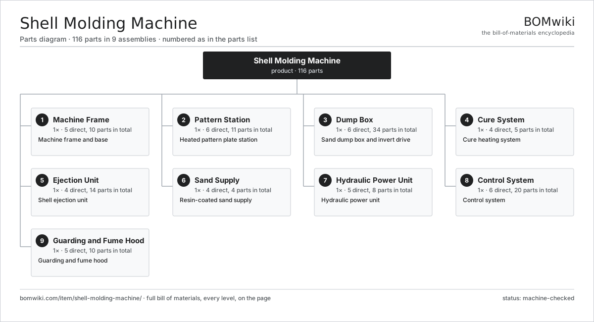
| # | Part | Qty | What it does |
|---|---|---|---|
| 1 | Machine Frame 5 parts | 1× | Machine frame and base |
| 2 | Pattern Station 6 parts | 1× | Heated pattern plate station |
| 3 | Dump Box 6 parts | 1× | Sand dump box and invert drive |
| 4 | Cure System 4 parts | 1× | Cure heating system |
| 5 | Ejection Unit 4 parts | 1× | Shell ejection unit |
| 6 | Sand Supply 4 parts | 1× | Resin-coated sand supply |
| 7 | Hydraulic Power Unit 5 parts | 1× | Hydraulic power unit |
| 8 | Control System 6 parts | 1× | Control system |
| 9 | Guarding and Fume Hood 5 parts | 1× | Guarding and fume hood |
3D model
No 3D model yet. Have a CAD file of this? Add a 3D model — STL renders right on this page; STEP, FreeCAD, and OpenSCAD sources are welcome too (openly licensed, like all 3D models on BOMwiki).
Build & assembly graph
expand / collapse · shared sub-assemblies converge · links to related products · est. labourTap an assembly to expand/collapse · tap a part to open it · use “Open page” for any node · drag to pan, scroll to zoom.
Bill of materials for Shell Molding Machine
9 top-level lines · 65 rows shown · 116 parts total · indented to 3 levels| # | Item / sub-assembly | Part no. | Qty/assy | Ext. qty | Parts | Type |
|---|---|---|---|---|---|---|
| 1 | Machine Frame 5 parts | shell-molding-machine-frame | 1× | 1 | 10 | assembly |
| 1.1 | Base Weldment | shell-molding-machine-base-weldment | 1× | 1 | · | part |
| 1.2 | Guide Column | shell-molding-machine-column | 2× | 2 | · | part |
| 1.3 | Cross Beam | shell-molding-machine-cross-beam | 1× | 1 | · | part |
| 1.4 | Leveling Foot | shell-molding-machine-leveling-foot | 4× | 4 | · | part |
| 1.5 | Fastener Set | fastener-set | 2× | 2 | · | part |
| 2 | Pattern Station 6 parts | shell-molding-machine-pattern-station | 1× | 1 | 11 | assembly |
| 2.1 | Pattern Plate | shell-molding-machine-pattern-plate | 1× | 1 | · | part |
| 2.2 | Cartridge Heater | shell-molding-machine-plate-heater | 4× | 4 | · | part |
| 2.3 | Pattern Carriage | shell-molding-machine-plate-carriage | 1× | 1 | · | part |
| 2.4 | Release Sprayer | shell-molding-machine-release-spray | 1× | 1 | · | part |
| 2.5 | Thermocouple | shell-molding-machine-thermocouple | 2× | 2 | · | part |
| 2.6 | Linear Guide Rail | linear-guide | 2× | 2 | · | part |
| 3 | Dump Box 6 parts | shell-molding-machine-dump-box | 1× | 1 | 34 | assembly |
| 3.1 | Box Shell | shell-molding-machine-box-shell | 1× | 1 | · | part |
| 3.2 | Clamp Frame | shell-molding-machine-clamp-frame | 1× | 1 | · | part |
| 3.3 | Invert Shaft | shell-molding-machine-invert-shaft | 1× | 1 | · | part |
| 3.4 | Invert Drive 4 parts | shell-molding-machine-invert-gearbox | 1× | 1 | 28 | assembly |
| 3.4.1 | Gearbox Housing | gearbox-housing | 1× | 1 | · | part |
| 3.4.2 | Helical Gear Pair | gear-pair | 1× | 1 | · | part |
| 3.4.3 | Servo Motor 4 parts + deeper › | servo-motor | 1× | 1 | 24 | assembly |
| 3.4.4 | Ball Bearing | ball-bearing | 2× | 2 | · | part |
| 3.5 | Invert Cylinder | shell-molding-machine-invert-cylinder | 1× | 1 | · | part |
| 3.6 | Ball Bearing | ball-bearing | 2× | 2 | · | part |
| 4 | Cure System 4 parts | shell-molding-machine-cure-system | 1× | 1 | 5 | assembly |
| 4.1 | Cure Controller | shell-molding-machine-cure-controller | 1× | 1 | · | part |
| 4.2 | Dwell Timer | shell-molding-machine-dwell-timer | 1× | 1 | · | part |
| 4.3 | Heating Element | heating-element | 1× | 1 | · | part |
| 4.4 | Solid-State Relay | shell-molding-machine-ssr | 2× | 2 | · | part |
| 5 | Ejection Unit 4 parts | shell-molding-machine-ejection | 1× | 1 | 14 | assembly |
| 5.1 | Ejector Plate | shell-molding-machine-eject-plate | 1× | 1 | · | part |
| 5.2 | Ejector Pin | shell-molding-machine-eject-pin | 8× | 8 | · | part |
| 5.3 | Ejection Cylinder | shell-molding-machine-eject-cylinder | 1× | 1 | · | part |
| 5.4 | Coil Spring | coil-spring | 4× | 4 | · | part |
| 6 | Sand Supply 4 parts | shell-molding-machine-sand-supply | 1× | 1 | 4 | assembly |
| 6.1 | Sand Hopper | shell-molding-machine-sand-hopper | 1× | 1 | · | part |
| 6.2 | Fill Gate | shell-molding-machine-fill-gate | 1× | 1 | · | part |
| 6.3 | Level Sensor | shell-molding-machine-level-sensor | 1× | 1 | · | part |
| 6.4 | Hopper Vibrator | shell-molding-machine-vibrator | 1× | 1 | · | part |
| 7 | Hydraulic Power Unit 5 parts | shell-molding-machine-hydraulics | 1× | 1 | 8 | assembly |
| 7.1 | Hydraulic Pump | shell-molding-machine-hpu-pump | 1× | 1 | · | part |
| 7.2 | Pump Motor | shell-molding-machine-hpu-motor | 1× | 1 | · | part |
| 7.3 | Oil Tank | shell-molding-machine-hpu-tank | 1× | 1 | · | part |
| 7.4 | Directional Valve | shell-molding-machine-hpu-valve | 4× | 4 | · | part |
| 7.5 | O-Ring Set | oring-set | 1× | 1 | · | part |
| 8 | Control System 6 parts | shell-molding-machine-control | 1× | 1 | 20 | assembly |
| 8.1 | PLC 4 parts | shell-molding-machine-plc | 1× | 1 | 7 | assembly |
| 8.1.1 | Bare PCB | pcb-bare | 1× | 1 | · | part |
| 8.1.2 | Microcontroller | mcu | 1× | 1 | · | part |
| 8.1.3 | SMD Passive (R/C/L) | smd-passives | 1× | 1 | · | part |
| 8.1.4 | Relay | relay | 4× | 4 | · | part |
| 8.2 | Operator HMI 3 parts | shell-molding-machine-hmi | 1× | 1 | 3 | assembly |
| 8.2.1 | LCD Panel | lcd-panel | 1× | 1 | · | part |
| 8.2.2 | Microcontroller | mcu | 1× | 1 | · | part |
| 8.2.3 | Bare PCB | pcb-bare | 1× | 1 | · | part |
| 8.3 | Power Supply | power-supply | 1× | 1 | · | part |
| 8.4 | E-Stop Button | shell-molding-machine-estop | 2× | 2 | · | part |
| 8.5 | Wire Bundle | wire-bundle | 1× | 1 | · | part |
| 8.6 | Connector | connector | 6× | 6 | · | part |
| 9 | Guarding and Fume Hood 5 parts | shell-molding-machine-guarding | 1× | 1 | 10 | assembly |
| 9.1 | Guard Panel | shell-molding-machine-guard-panel | 4× | 4 | · | part |
| 9.2 | Fume Hood | shell-molding-machine-fume-hood | 1× | 1 | · | part |
| 9.3 | Extraction Fan | shell-molding-machine-extract-fan | 1× | 1 | · | part |
| 9.4 | Interlock Switch | shell-molding-machine-door-switch | 2× | 2 | · | part |
| 9.5 | Sheet Metal Panel | sheet-panel | 2× | 2 | · | part |
Related products
same domain, ranked by shared parts Rubber Extrusion Line
524 parts · shares 24 with this page
Powder Coating Line
5,418 parts · shares 24 with this page
Casting Fettling Machine
802 parts · shares 23 with this page
Wax Pattern Injection Press
107 parts · shares 23 with this page
Hammer Mill
790 parts · shares 21 with this page
Rubber Extrusion Line
524 parts · shares 24 with this page
Powder Coating Line
5,418 parts · shares 24 with this page
Casting Fettling Machine
802 parts · shares 23 with this page
Wax Pattern Injection Press
107 parts · shares 23 with this page
Hammer Mill
790 parts · shares 21 with this page
Sourcing: possible vendors
Prices, MOQ, and lead times are algorithmic estimates, not quotes, and not claims about these companies. Company mappings are curated by keyword; est. price band $5k–$2M. How estimates work| Vendor | HQ | Specialty | MOQ | Lead time |
|---|---|---|---|---|
| atlascopco.com ↗ | Stockholm, SE | Compressors & industrial | 10 units | 12–20 wks |
|
🇦🇹Andritz
andritz.com ↗
|
Graz, AT | Process plants & machinery | 10 units | 12–20 wks |
| buhlergroup.com ↗ | Uzwil, CH | Food & materials processing | 10 units | 12–20 wks |
| gea.com ↗ | Düsseldorf, DE | Process technology | 10 units | 12–20 wks |
| mhi.com ↗ | Tokyo, JP | Heavy machinery | 10 units | 12–20 wks |
1,012-word article