Ultrasonic Welding Machine
ProductAlso known as: Ultrasonic Plastic Welding Machine
Overview
An ultrasonic plastic welder joins two thermoplastic parts by vibrating them against each other thousands of times a second until friction at the joint melts a thin film of plastic, which then solidifies into a weld. No glue, solvent, or added material is involved, and the whole weld takes a fraction of a second. The machine presses an ultrasonic tool, the horn, onto the upper part, drives it to vibrate at 20 to 40 kHz, and the energy concentrates at a small molded feature in the joint so the plastic melts exactly where it should. Ultrasonic welding is the standard way to assemble plastic housings, medical devices, automotive parts, filters, and packaging at high speed.
The machine has two halves: a press that applies force and a high-frequency drive train that supplies vibration. The Press Frame and Pneumatic Actuator bring the horn down with a set force, the Ultrasonic Stack converts electrical drive into vibration, the Ultrasonic Generator powers the stack, the Part Fixture and Anvil holds the lower part, and the Welder Control System system runs and records each weld.
The ultrasonic stack
The heart of the machine is the Ultrasonic Stack, a resonant column of three tuned parts. At the top, the Piezoelectric Converter holds a set of Piezoelectric Element discs clamped between a Front Driver Mass and a Back Mass by a Tie Bolt; when driven with high-frequency voltage the discs change thickness and the whole converter vibrates along its axis. Below it, the Booster is a tuned bar that scales the amplitude up or down. At the bottom, the Welding Horn is a precisely machined tool, usually titanium, shaped to match the part and to resonate at the working frequency. Every piece is a half wavelength long so the whole column resonates together; if the horn is re-cut or changed, it must be tuned back to frequency or the stack will not run.
How the weld forms
The weld depends on a small molded feature called an energy director, a thin triangular rib on one part. When the horn presses the parts together and starts vibrating, almost all the energy concentrates at the tip of that rib because it is the only point of contact. The rib heats, melts, and flows along the joint, and as the molten plastic spreads the two parts collapse together until the joint is filled and welded. A shear joint is the other common design, where a small interference between the parts melts and wipes as they telescope together, giving a strong hermetic seal. The Anvil under the part is rigid so it reflects the vibration back into the joint rather than soaking it up; a soft or loose fixture wastes energy and gives a weak weld.
Force, motion, and generator
The press supplies the force that turns vibration into a weld. The Pneumatic Actuator uses an Air Cylinder whose pressure, set by the Pressure Regulator, decides the weld force, while Flow Control valves set how fast the head comes down. A Trigger Switch starts the ultrasound only once the horn meets the part at the set force, and an Travel Encoder measures how far the parts collapse so the weld can be ended by distance. The Ultrasonic Generator drives the stack: a Power Amplifier Board amplifier supplies the high-frequency current, and a Frequency Tracking Board keeps the drive locked to the stack resonance and holds amplitude steady as the load changes during the weld, because the resonant frequency shifts slightly as the horn warms and the part melts.
Control modes and fixturing
Repeatable welds come from controlling the right variable. The Welder Control System system can weld by time, by total energy delivered, by collapse distance, or by peak power, and good practice chooses the mode that best tracks weld strength for the part. Energy and distance control give more consistent results than time alone because they adapt to part-to-part variation. The Part Fixture and Anvil must hold the lower part rigidly and exactly: a machined Part Nest cradles it, Locating Pin features register the energy directors under the horn, and Part Clamp hardware keeps the part from walking under vibration. Each weld is logged so a line can flag a bad part immediately.
Use and limits
Ultrasonic welders run on assembly lines for electronics enclosures, medical disposables, automotive trim and clips, blister packs, filters, and toys, often welding several parts a second. Their strengths are speed, no consumables, clean weld zones with no glue, and tight process control that suits regulated products. The limits follow from the physics: the parts must be thermoplastic and designed with an energy director or shear joint, the horn is part-specific tooling that must be tuned, and large or far-apart joints need staking, multiple horns, or a different process such as the Hot Plate Plastic Welder for thick or high-temperature joints. For small to medium plastic assemblies designed for it, ultrasonic welding is the fastest and most controllable joining method available.
Ultrasonic Welding Machine parts and their functions
7 top-level parts · 269 parts in total · full bill of materials below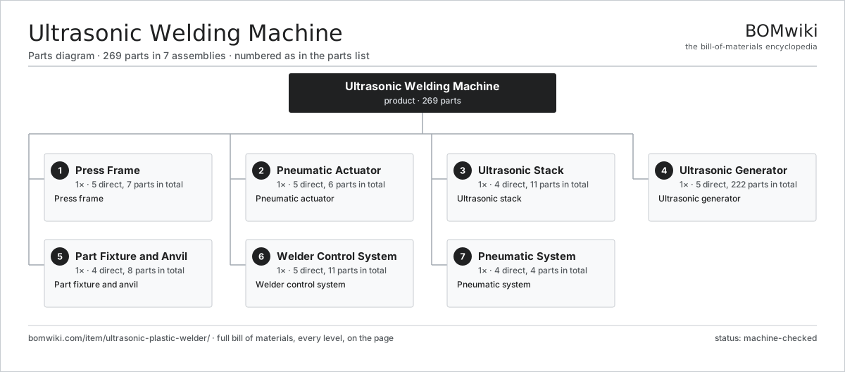
| # | Part | Qty | What it does |
|---|---|---|---|
| 1 | Press Frame 5 parts | 1× | Press frame |
| 2 | Pneumatic Actuator 5 parts | 1× | Pneumatic actuator |
| 3 | Ultrasonic Stack 4 parts | 1× | Ultrasonic stack |
| 4 | Ultrasonic Generator 5 parts | 1× | Ultrasonic generator |
| 5 | Part Fixture and Anvil 4 parts | 1× | Part fixture and anvil |
| 6 | Welder Control System 5 parts | 1× | Welder control system |
| 7 | Pneumatic System 4 parts | 1× | Pneumatic system |
3D model
No 3D model yet. Have a CAD file of this? Add a 3D model — STL renders right on this page; STEP, FreeCAD, and OpenSCAD sources are welcome too (openly licensed, like all 3D models on BOMwiki).
Build & assembly graph
expand / collapse · shared sub-assemblies converge · links to related products · est. labourTap an assembly to expand/collapse · tap a part to open it · use “Open page” for any node · drag to pan, scroll to zoom.
Bill of materials for Ultrasonic Welding Machine
7 top-level lines · 50 rows shown · 269 parts total · indented to 3 levels| # | Item / sub-assembly | Part no. | Qty/assy | Ext. qty | Parts | Type |
|---|---|---|---|---|---|---|
| 1 | Press Frame 5 parts | ultrasonic-plastic-welder-frame | 1× | 1 | 7 | assembly |
| 1.1 | Base Plate | ultrasonic-plastic-welder-base-plate | 1× | 1 | · | part |
| 1.2 | Support Column | ultrasonic-plastic-welder-column | 1× | 1 | · | part |
| 1.3 | Head Slide | ultrasonic-plastic-welder-head-slide | 1× | 1 | · | part |
| 1.4 | Linear Guide Rail | linear-guide | 2× | 2 | · | part |
| 1.5 | Fastener Set | fastener-set | 2× | 2 | · | part |
| 2 | Pneumatic Actuator 5 parts | ultrasonic-plastic-welder-actuator | 1× | 1 | 6 | assembly |
| 2.1 | Air Cylinder | ultrasonic-plastic-welder-air-cylinder | 1× | 1 | · | part |
| 2.2 | Flow Control | ultrasonic-plastic-welder-flow-control | 2× | 2 | · | part |
| 2.3 | Travel Encoder | ultrasonic-plastic-welder-encoder | 1× | 1 | · | part |
| 2.4 | Trigger Switch | ultrasonic-plastic-welder-trigger-switch | 1× | 1 | · | part |
| 2.5 | O-Ring Set | oring-set | 1× | 1 | · | part |
| 3 | Ultrasonic Stack 4 parts | ultrasonic-plastic-welder-stack | 1× | 1 | 11 | assembly |
| 3.1 | Piezoelectric Converter 4 parts | ultrasonic-plastic-welder-converter | 1× | 1 | 7 | assembly |
| 3.1.1 | Piezoelectric Element | piezo-element | 4× | 4 | · | part |
| 3.1.2 | Front Driver Mass | ultrasonic-plastic-welder-front-mass | 1× | 1 | · | part |
| 3.1.3 | Back Mass | ultrasonic-plastic-welder-back-mass | 1× | 1 | · | part |
| 3.1.4 | Tie Bolt | ultrasonic-plastic-welder-tie-bolt | 1× | 1 | · | part |
| 3.2 | Booster | ultrasonic-plastic-welder-booster | 1× | 1 | · | part |
| 3.3 | Welding Horn | ultrasonic-plastic-welder-horn | 1× | 1 | · | part |
| 3.4 | Coupling Stud | ultrasonic-plastic-welder-stud | 2× | 2 | · | part |
| 4 | Ultrasonic Generator 5 parts | ultrasonic-plastic-welder-generator | 1× | 1 | 222 | assembly |
| 4.1 | Power Amplifier Board 4 parts | ultrasonic-plastic-welder-power-board | 1× | 1 | 127 | assembly |
| 4.1.1 | Bare PCB | pcb-bare | 1× | 1 | · | part |
| 4.1.2 | Power MOSFET | mosfet | 4× | 4 | · | part |
| 4.1.3 | Gate Driver IC | gate-driver-ic | 2× | 2 | · | part |
| 4.1.4 | SMD Passive (R/C/L) | smd-passives | 120× | 120 | · | part |
| 4.2 | Frequency Tracking Board 3 parts | ultrasonic-plastic-welder-tracking-board | 1× | 1 | 92 | assembly |
| 4.2.1 | Bare PCB | pcb-bare | 1× | 1 | · | part |
| 4.2.2 | Microcontroller | mcu | 1× | 1 | · | part |
| 4.2.3 | SMD Passive (R/C/L) | smd-passives | 90× | 90 | · | part |
| 4.3 | Matching Transformer | ultrasonic-plastic-welder-match-transformer | 1× | 1 | · | part |
| 4.4 | Power Supply | power-supply | 1× | 1 | · | part |
| 4.5 | Generator Housing | ultrasonic-plastic-welder-gen-housing | 1× | 1 | · | part |
| 5 | Part Fixture and Anvil 4 parts | ultrasonic-plastic-welder-fixture | 1× | 1 | 8 | assembly |
| 5.1 | Part Nest | ultrasonic-plastic-welder-nest | 1× | 1 | · | part |
| 5.2 | Anvil | ultrasonic-plastic-welder-anvil | 1× | 1 | · | part |
| 5.3 | Locating Pin | ultrasonic-plastic-welder-locating-pin | 4× | 4 | · | part |
| 5.4 | Part Clamp | ultrasonic-plastic-welder-clamp | 2× | 2 | · | part |
| 6 | Welder Control System 5 parts | ultrasonic-plastic-welder-control | 1× | 1 | 11 | assembly |
| 6.1 | Weld Controller | ultrasonic-plastic-welder-controller | 1× | 1 | · | part |
| 6.2 | Operator Panel | ultrasonic-plastic-welder-hmi | 1× | 1 | · | part |
| 6.3 | Relay | relay | 4× | 4 | · | part |
| 6.4 | Wire Bundle | wire-bundle | 1× | 1 | · | part |
| 6.5 | Connector | connector | 4× | 4 | · | part |
| 7 | Pneumatic System 4 parts | ultrasonic-plastic-welder-pneumatics | 1× | 1 | 4 | assembly |
| 7.1 | Pressure Regulator | ultrasonic-plastic-welder-regulator | 1× | 1 | · | part |
| 7.2 | Air Filter | ultrasonic-plastic-welder-filter | 1× | 1 | · | part |
| 7.3 | Solenoid Valve | ultrasonic-plastic-welder-solenoid | 1× | 1 | · | part |
| 7.4 | Pressure Sensor | pressure-sensor | 1× | 1 | · | part |
Related products
same domain, ranked by shared parts Dynamic Balancing Machine
573 parts · shares 10 with this page
Dynamic Balancing Machine
573 parts · shares 10 with this page
 Industrial 3D Printer
218 parts · shares 6 with this page
Casting Fettling Machine
802 parts · shares 8 with this page
Industrial 3D Printer
218 parts · shares 6 with this page
Casting Fettling Machine
802 parts · shares 8 with this page
 Vibratory Bowl Feeder
59 parts · shares 5 with this page
Vibratory Bowl Feeder
59 parts · shares 5 with this page
 Investment Casting Shell Line
869 parts · shares 8 with this page
Investment Casting Shell Line
869 parts · shares 8 with this page
 Injection Molding Machine
292 parts · shares 7 with this page
Injection Molding Machine
292 parts · shares 7 with this page
Sourcing: possible vendors
Prices, MOQ, and lead times are algorithmic estimates, not quotes, and not claims about these companies. Company mappings are curated by keyword; est. price band $5k–$2M. How estimates work| Vendor | HQ | Specialty | MOQ | Lead time |
|---|---|---|---|---|
| atlascopco.com ↗ | Stockholm, SE | Compressors & industrial | 10 units | 12–20 wks |
|
🇦🇹Andritz
andritz.com ↗
|
Graz, AT | Process plants & machinery | 10 units | 12–20 wks |
| buhlergroup.com ↗ | Uzwil, CH | Food & materials processing | 10 units | 12–20 wks |
| gea.com ↗ | Düsseldorf, DE | Process technology | 10 units | 12–20 wks |
| mhi.com ↗ | Tokyo, JP | Heavy machinery | 10 units | 12–20 wks |
895-word article