Rubber Internal Mixer
ProductOverview
A rubber internal mixer compounds raw elastomer with fillers, oils, and curatives inside a sealed chamber, working the batch under heat and high shear. It is the first heavy machine in most rubber factories, feeding mills, extruders, and calenders downstream. The dominant design is the Banbury-type tangential mixer; intermeshing designs are also common where tight temperature control matters. Net chamber volumes run from about 1.5 liters on a laboratory unit to 600 liters on a production tyre line.
The machine charges polymer bales, carbon black or silica, process oils, and chemicals through a hopper, presses them down with a ram, and shears the mass between two rotors and the chamber wall. Mechanical work converts to heat, so the chamber, rotors, and discharge door are all water-cooled. When the batch reaches a target temperature or absorbs a target amount of energy, the bottom door drops and releases the compound.
How it works
The operator or an automatic feed station charges the Charging Hopper with weighed polymer and fillers. The Feed Door closes and the Ram Cylinder drives the Ram Head down to seal the throat and force material into the rotor zone. Ram pressure holds the batch against the rotors so no pocket escapes the shear field.
The Main Drive Motor turns the two Rotor Shaft members through the reduction gearbox built around the Gearbox Housing and its Helical Gear Pair stages. The rotors run at slightly different speeds, the friction ratio, which adds extra shear as material passes between them. Each Rotor Wing drags compound around the bore, and the Wing Tip Insert forces it through the narrow clearance against the Bore Liner, where dispersive mixing breaks down filler agglomerates.
The Power Monitor watches main motor power, which tracks batch viscosity and state of mix. The Stock Thermocouple reads stock temperature. The Mixer PLC runs a recipe that may raise the ram briefly to add oil through the Oil Injection Port, change rotor speed, or hold for a set energy input. When the endpoint is met, the Door Hydraulic Latch releases and the Drop Door Body swings open, dropping the batch onto a mill or conveyor.
Rotors and chamber
The rotors are the heart of the machine. Each Rotor Shaft is a forged alloy steel body carrying two or four helical wings. Tangential rotors run in separate bores and rely on the chamber wall for shear; intermeshing rotors interlock and are kept phased by the Rotor Timing Gear so the wings clear each other. Wing tips wear fastest, so the Wing Tip Insert is usually a hardfaced replaceable insert.
The Chamber Body is a cast steel housing with twin overlapping bores. Bolt-in Bore Liner plates take the abrasion from filler-loaded compound and are renewed when clearances open up. Both rotors and chamber carry water passages: the Rotor Cooling Bore inside each rotor and the Chamber Cooling Jacket in the walls. Water reaches the spinning rotors through a Rotor Rotary Union at each shaft end. At the rotor exits, the Rotor Dust Seal keeps compound from packing into the Ball Bearing and contaminating the Oil Seal.
Ram, feed, and discharge
The Ram and Floating Weight is a floating weight. Pneumatic rams use 4–8 bar air; hydraulic rams from the Hydraulic Power Unit unit reach higher pressure for dense compounds. A Ram Position Sensor reports ram height, which falls as fillers wet out, giving an early read on mix progress. A Pressure Sensor confirms the ram is seated.
Discharge is through the Drop Door. The Drop Door Body forms the chamber floor during mixing, held shut by the hydraulic Door Hydraulic Latch against the full batch load. A Drop Door Liner takes the wear, and a Door Cooling Jacket cools the door face. The Hydraulic Power Unit unit supplies its Hydraulic Accumulator so latch pressure holds through the cycle.
Materials and variants
Compounds range from natural rubber and SBR through nitrile, EPDM, and silicone, loaded with carbon black, silica, clay, and process oils. Rotor and chamber steels are chosen for abrasion resistance, with hardfacing on the wing tips. Mixers split into tangential (Banbury style, robust and tolerant) and intermeshing (better temperature control for heat-sensitive silica masterbatch). Many plants run a tandem line: an internal mixer makes the masterbatch, drops to a second mixer or a mill for curative addition at lower temperature, which protects against scorch.
Use and applications
Internal mixers serve tyre plants, hose and belt makers, seal and gasket producers, and technical rubber goods. A tyre factory may run several mixers feeding twin-screw extruders and Rubber Calender lines. Cycle times are short, 90–300 seconds, so a single large mixer produces many tonnes per shift.
Maintenance and failure modes
The main wear items are the Wing Tip Insert, Bore Liner, and Drop Door Liner; clearance growth shows up as falling shear and longer cycles. The Rotor Dust Seal is critical: a failed seal lets compound migrate into the bearings, and seal water leaks contaminate the Lubrication System grease. Cooling faults track to scaled Rotor Cooling Bore passages or a worn Rotor Rotary Union, which raise discharge temperature and risk scorch. The Hydraulic Power Unit unit needs clean oil through its Hydraulic Filter so the door latch and ram respond predictably. Gearbox condition is tracked through oil analysis and vibration on the Drive Train bearings.
Rubber Internal Mixer parts and their functions
10 top-level parts · 122 parts in total · full bill of materials below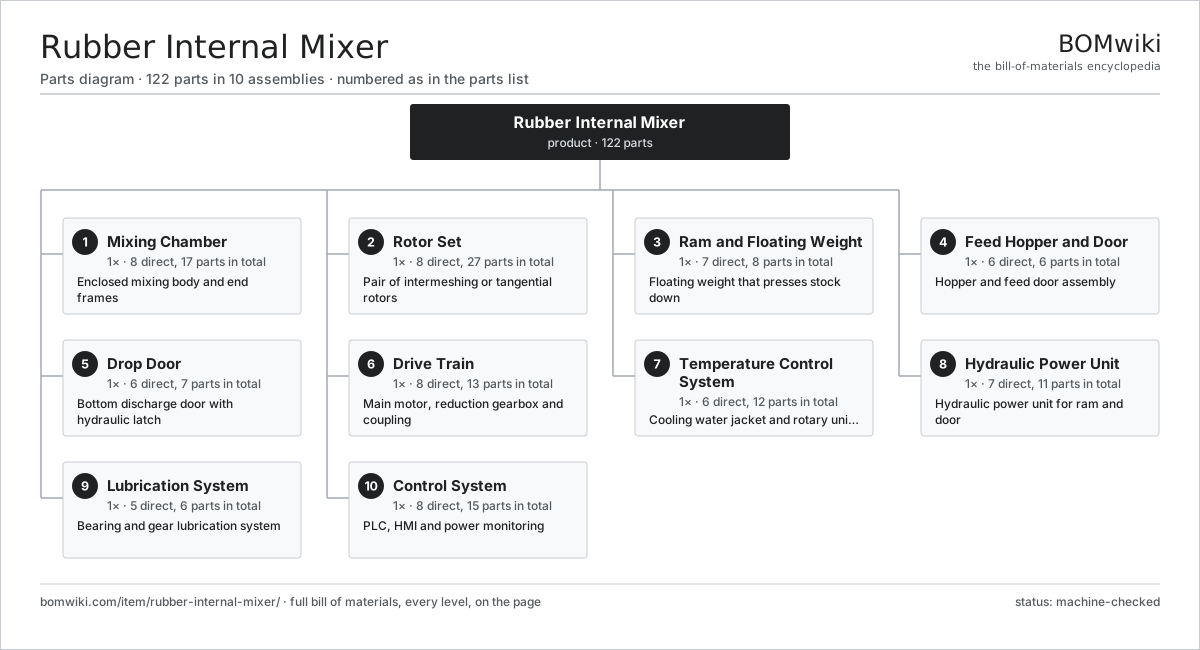
| # | Part | Qty | What it does |
|---|---|---|---|
| 1 | Mixing Chamber 8 parts | 1× | Enclosed mixing body and end frames |
| 2 | Rotor Set 8 parts | 1× | Pair of intermeshing or tangential rotors |
| 3 | Ram and Floating Weight 7 parts | 1× | Floating weight that presses stock down |
| 4 | Feed Hopper and Door 6 parts | 1× | Hopper and feed door assembly |
| 5 | Drop Door 6 parts | 1× | Bottom discharge door with hydraulic latch |
| 6 | Drive Train 8 parts | 1× | Main motor, reduction gearbox and coupling |
| 7 | Temperature Control System 6 parts | 1× | Cooling water jacket and rotary unions |
| 8 | Hydraulic Power Unit 7 parts | 1× | Hydraulic power unit for ram and door |
| 9 | Lubrication System 5 parts | 1× | Bearing and gear lubrication system |
| 10 | Control System 8 parts | 1× | PLC, HMI and power monitoring |
3D model
No 3D model yet. Have a CAD file of this? Add a 3D model — STL renders right on this page; STEP, FreeCAD, and OpenSCAD sources are welcome too (openly licensed, like all 3D models on BOMwiki).
Build & assembly graph
expand / collapse · shared sub-assemblies converge · links to related products · est. labourTap an assembly to expand/collapse · tap a part to open it · use “Open page” for any node · drag to pan, scroll to zoom.
Bill of materials for Rubber Internal Mixer
10 top-level lines · 79 rows shown · 122 parts total · indented to 3 levels| # | Item / sub-assembly | Part no. | Qty/assy | Ext. qty | Parts | Type |
|---|---|---|---|---|---|---|
| 1 | Mixing Chamber 8 parts | rubber-internal-mixer-chamber | 1× | 1 | 17 | assembly |
| 1.1 | Chamber Body | rubber-internal-mixer-chamber-body | 1× | 1 | · | part |
| 1.2 | End Side Frame | rubber-internal-mixer-side-frame | 2× | 2 | · | part |
| 1.3 | Bore Liner | rubber-internal-mixer-chamber-liner | 2× | 2 | · | part |
| 1.4 | Chamber End Plate | rubber-internal-mixer-end-plate | 2× | 2 | · | part |
| 1.5 | Rotor Dust Seal | rubber-internal-mixer-dust-seal | 4× | 4 | · | part |
| 1.6 | Throat Saddle | rubber-internal-mixer-saddle | 1× | 1 | · | part |
| 1.7 | Chamber Cooling Jacket | rubber-internal-mixer-chamber-jacket | 1× | 1 | · | part |
| 1.8 | Fastener Set | fastener-set | 4× | 4 | · | part |
| 2 | Rotor Set 8 parts | rubber-internal-mixer-rotors | 1× | 1 | 27 | assembly |
| 2.1 | Rotor Shaft | rubber-internal-mixer-rotor-shaft | 2× | 2 | · | part |
| 2.2 | Rotor Wing | rubber-internal-mixer-rotor-wing | 4× | 4 | · | part |
| 2.3 | Wing Tip Insert | rubber-internal-mixer-rotor-tip | 8× | 8 | · | part |
| 2.4 | Rotor Cooling Bore | rubber-internal-mixer-rotor-bore | 2× | 2 | · | part |
| 2.5 | Rotor Timing Gear | rubber-internal-mixer-timing-gear | 1× | 1 | · | part |
| 2.6 | Ball Bearing | ball-bearing | 4× | 4 | · | part |
| 2.7 | Oil Seal | oil-seal | 4× | 4 | · | part |
| 2.8 | Rotor Rotary Union | rubber-internal-mixer-rotary-union | 2× | 2 | · | part |
| 3 | Ram and Floating Weight 7 parts | rubber-internal-mixer-ram | 1× | 1 | 8 | assembly |
| 3.1 | Ram Cylinder | rubber-internal-mixer-ram-cylinder | 1× | 1 | · | part |
| 3.2 | Ram Head | rubber-internal-mixer-ram-head | 1× | 1 | · | part |
| 3.3 | Ram Piston Rod | rubber-internal-mixer-ram-rod | 1× | 1 | · | part |
| 3.4 | Ram Guide Bar | rubber-internal-mixer-ram-guide | 2× | 2 | · | part |
| 3.5 | Pressure Sensor | pressure-sensor | 1× | 1 | · | part |
| 3.6 | Ram Position Sensor | rubber-internal-mixer-position-sensor | 1× | 1 | · | part |
| 3.7 | O-Ring Set | oring-set | 1× | 1 | · | part |
| 4 | Feed Hopper and Door 6 parts | rubber-internal-mixer-feed | 1× | 1 | 6 | assembly |
| 4.1 | Charging Hopper | rubber-internal-mixer-hopper | 1× | 1 | · | part |
| 4.2 | Feed Door | rubber-internal-mixer-feed-door | 1× | 1 | · | part |
| 4.3 | Feed Door Cylinder | rubber-internal-mixer-door-cylinder | 1× | 1 | · | part |
| 4.4 | Oil Injection Port | rubber-internal-mixer-oil-injector | 1× | 1 | · | part |
| 4.5 | Hopper Dust Hood | rubber-internal-mixer-dust-stop | 1× | 1 | · | part |
| 4.6 | Fastener Set | fastener-set | 1× | 1 | · | part |
| 5 | Drop Door 6 parts | rubber-internal-mixer-drop-door | 1× | 1 | 7 | assembly |
| 5.1 | Drop Door Body | rubber-internal-mixer-door-body | 1× | 1 | · | part |
| 5.2 | Drop Door Liner | rubber-internal-mixer-door-liner | 1× | 1 | · | part |
| 5.3 | Door Hydraulic Latch | rubber-internal-mixer-door-latch | 1× | 1 | · | part |
| 5.4 | Door Pivot Bearing | rubber-internal-mixer-door-pivot | 1× | 1 | · | part |
| 5.5 | Door Cooling Jacket | rubber-internal-mixer-door-jacket | 1× | 1 | · | part |
| 5.6 | Door Limit Switch | rubber-internal-mixer-limit-switch | 2× | 2 | · | part |
| 6 | Drive Train 8 parts | rubber-internal-mixer-drive | 1× | 1 | 13 | assembly |
| 6.1 | Main Drive Motor | rubber-internal-mixer-main-motor | 1× | 1 | · | part |
| 6.2 | Gearbox Housing | gearbox-housing | 1× | 1 | · | part |
| 6.3 | Helical Gear Pair | gear-pair | 2× | 2 | · | part |
| 6.4 | Drive Coupling | rubber-internal-mixer-coupling | 1× | 1 | · | part |
| 6.5 | Drive Flywheel | rubber-internal-mixer-flywheel | 1× | 1 | · | part |
| 6.6 | Drive Brake | rubber-internal-mixer-brake | 1× | 1 | · | part |
| 6.7 | Ball Bearing | ball-bearing | 4× | 4 | · | part |
| 6.8 | Oil Seal | oil-seal | 2× | 2 | · | part |
| 7 | Temperature Control System 6 parts | rubber-internal-mixer-tempctrl | 1× | 1 | 12 | assembly |
| 7.1 | Cooling Water Pump | rubber-internal-mixer-water-pump | 1× | 1 | · | part |
| 7.2 | Cooling Zone Valve | rubber-internal-mixer-water-valve | 3× | 3 | · | part |
| 7.3 | Cooling Heat Exchanger | rubber-internal-mixer-heat-exchanger | 1× | 1 | · | part |
| 7.4 | Stock Thermocouple | rubber-internal-mixer-thermocouple | 4× | 4 | · | part |
| 7.5 | Cooling Flow Meter | rubber-internal-mixer-flow-meter | 2× | 2 | · | part |
| 7.6 | Water Manifold | rubber-internal-mixer-manifold | 1× | 1 | · | part |
| 8 | Hydraulic Power Unit 7 parts | rubber-internal-mixer-hydraulic | 1× | 1 | 11 | assembly |
| 8.1 | Hydraulic Pump | rubber-internal-mixer-hyd-pump | 1× | 1 | · | part |
| 8.2 | Hydraulic Pump Motor | rubber-internal-mixer-hyd-motor | 1× | 1 | · | part |
| 8.3 | Hydraulic Reservoir | rubber-internal-mixer-hyd-tank | 1× | 1 | · | part |
| 8.4 | Hydraulic Valve | rubber-internal-mixer-hyd-valve | 4× | 4 | · | part |
| 8.5 | Hydraulic Accumulator | rubber-internal-mixer-accumulator | 1× | 1 | · | part |
| 8.6 | Pressure Sensor | pressure-sensor | 2× | 2 | · | part |
| 8.7 | Hydraulic Filter | rubber-internal-mixer-hyd-filter | 1× | 1 | · | part |
| 9 | Lubrication System 5 parts | rubber-internal-mixer-lube | 1× | 1 | 6 | assembly |
| 9.1 | Lubrication Pump | rubber-internal-mixer-lube-pump | 1× | 1 | · | part |
| 9.2 | Metering Block | rubber-internal-mixer-lube-block | 2× | 2 | · | part |
| 9.3 | Lubrication Line Set | rubber-internal-mixer-lube-line | 1× | 1 | · | part |
| 9.4 | Lubrication Monitor | rubber-internal-mixer-lube-sensor | 1× | 1 | · | part |
| 9.5 | Connector | connector | 1× | 1 | · | part |
| 10 | Control System 8 parts | rubber-internal-mixer-controls | 1× | 1 | 15 | assembly |
| 10.1 | Mixer PLC | rubber-internal-mixer-plc | 1× | 1 | · | part |
| 10.2 | LCD Panel | lcd-panel | 1× | 1 | · | part |
| 10.3 | Power Monitor | rubber-internal-mixer-power-monitor | 1× | 1 | · | part |
| 10.4 | Field I/O Module | rubber-internal-mixer-io-module | 2× | 2 | · | part |
| 10.5 | Power Supply | power-supply | 1× | 1 | · | part |
| 10.6 | Relay | relay | 6× | 6 | · | part |
| 10.7 | Wire Bundle | wire-bundle | 1× | 1 | · | part |
| 10.8 | Emergency Stop Station | rubber-internal-mixer-estop | 2× | 2 | · | part |
Related products
same domain, ranked by shared parts Industrial Parts Washer
423 parts · shares 10 with this page
Industrial Parts Washer
423 parts · shares 10 with this page
 Rubber Extrusion Line
524 parts · shares 10 with this page
Rubber Extrusion Line
524 parts · shares 10 with this page
 Foundry Sand Mixer
93 parts · shares 9 with this page
Foundry Sand Mixer
93 parts · shares 9 with this page
 Decanter Centrifuge
172 parts · shares 9 with this page
Decanter Centrifuge
172 parts · shares 9 with this page
Sourcing: possible vendors
Prices, MOQ, and lead times are algorithmic estimates, not quotes, and not claims about these companies. Company mappings are curated by keyword; est. price band $5k–$2M. How estimates work| Vendor | HQ | Specialty | MOQ | Lead time |
|---|---|---|---|---|
| atlascopco.com ↗ | Stockholm, SE | Compressors & industrial | 10 units | 12–20 wks |
|
🇦🇹Andritz
andritz.com ↗
|
Graz, AT | Process plants & machinery | 10 units | 12–20 wks |
| buhlergroup.com ↗ | Uzwil, CH | Food & materials processing | 10 units | 12–20 wks |
| gea.com ↗ | Düsseldorf, DE | Process technology | 10 units | 12–20 wks |
| mhi.com ↗ | Tokyo, JP | Heavy machinery | 10 units | 12–20 wks |
988-word article