Horizontal Injection Molding Machine
ProductOverview
A horizontal injection molding machine forms plastic parts by melting pellets and forcing the melt into a closed steel mold under high pressure, then cooling and ejecting the part. It is the most common machine layout in the plastics industry: the Injection Unit lies on the same horizontal axis as the Clamp Unit, so the screw injects sideways into a vertically split mold and parts drop out by gravity. The machine runs an automatic cycle: clamp closes, screw injects and holds, part cools while the screw recharges the next shot, clamp opens, and the Ejector System pushes the part out.
Injection unit
The Injection Unit does the melting and dosing. Pellets fall through a Water-Cooled Feed Throat into the Plasticizing Barrel, a nitrided steel tube wrapped in band heaters. Inside it the Reciprocating Screw turns, conveying pellets forward; shear from the Screw Body flights plus heat from the barrel melt the plastic into a uniform shot that collects ahead of the screw tip. A Non-Return Check Ring non-return valve lets melt pass forward during recharge but seals during injection so the screw can act as a plunger. To inject, the Injection Cylinder pair rams the screw forward, driving melt through the Injection Nozzle, which seats against the mold sprue. The Screw Rotation Drive hydraulic motor turns the screw during the recharge phase, and the Injection Carriage slides the whole unit so the nozzle can be retracted for purging.
Clamp unit
The Clamp Unit holds the mold halves shut against injection pressure, which can reach tens of tonnes of separating force. The mold's stationary half bolts to the Fixed Platen and the other half to the Moving Platen, which slides on four Tie Bar columns. A Toggle Linkage double-toggle linkage, driven by the Clamp Cylinder, multiplies the cylinder force into full clamp tonnage and locks near top-dead-center so the clamp holds with little continuous oil flow. The Toggle Link members and Toggle Pin joints carry the load. After cooling, the Ejector System drives Ejector Pin sets through the Ejector Plate to knock the part off the core.
Hydraulic and drive system
A horizontal machine of this class is hydraulically driven. The Hydraulic System centers on a Variable Displacement Pump, a variable-displacement unit turned by the Pump Motor, that delivers oil on demand to cut idling losses. The Valve Manifold uses Proportional Valve elements to ramp injection pressure and clamp speed smoothly, and Directional Valve elements to sequence the cylinders. An Accumulator supplies the fast injection stroke, and an Oil Cooler keeps tank temperature stable. Pressure feedback comes from a Pressure Sensor set so the controller can hold the programmed profile.
Heating and material feed
The melt profile is set by the Barrel Heating System: a Barrel Band Heater per zone, each built on a Heating Element, with a Zone Thermocouple feeding back so the controller holds typically 180 to 320 C depending on resin. The Material Feed System dries the pellets first, since many resins absorb moisture that would cause splay; the Desiccant Dryer runs hot air through a Desiccant Bed and the Vacuum Loader conveys dried pellets to the hopper under vacuum.
Control and safety
The Control System runs the whole cycle from the Machine Controller, closing loops on injection pressure, screw position read by a Linear Position Sensor, and barrel temperature. The operator sets shot size, hold pressure, and timing on the HMI Touchscreen. Because the clamp can crush, the Safety System interlocks the Sliding Safety Gate with the clamp through a Interlock Switch and a Light Curtain, and stops everything on the Emergency Stop.
Use and variants
Horizontal machines mold the bulk of everyday plastic parts: bottle caps, automotive trim, housings, connectors, and packaging. Tonnage is chosen from the projected part area times the cavity pressure, so a small connector runs on a 50 t machine while a bumper needs 1500 t or more. The toggle-clamp hydraulic design described here is the workhorse; servo-pump and all-electric variants replace the fixed-pump drive to cut energy and improve repeatability, and two-platen designs replace the toggle for very large tonnages. The mold itself is a separate tool, but the Base Frame platen pattern and Tie Bar spacing define what molds will fit.
The cycle has four phases the controller times in sequence: fill, where the Reciprocating Screw injects fast to fill the cavity; pack and hold, where pressure is held to feed shrinkage as the part cools; cooling, the longest phase, during which the screw recharges the next shot; and ejection. Setting the changeover point from fill to hold, usually by screw position read at the Linear Position Sensor, is one of the key process adjustments, because switching too early starves the part and too late flashes it. Resins also dictate barrel temperature: polypropylene runs near 220 C, polycarbonate near 300 C, and each needs the Material Feed System drying matched to how much moisture it absorbs. Mold cooling is plumbed separately through channels in the tool, fed from a chiller off the machine.
Horizontal Injection Molding Machine parts and their functions
8 top-level parts · 301 parts in total · full bill of materials below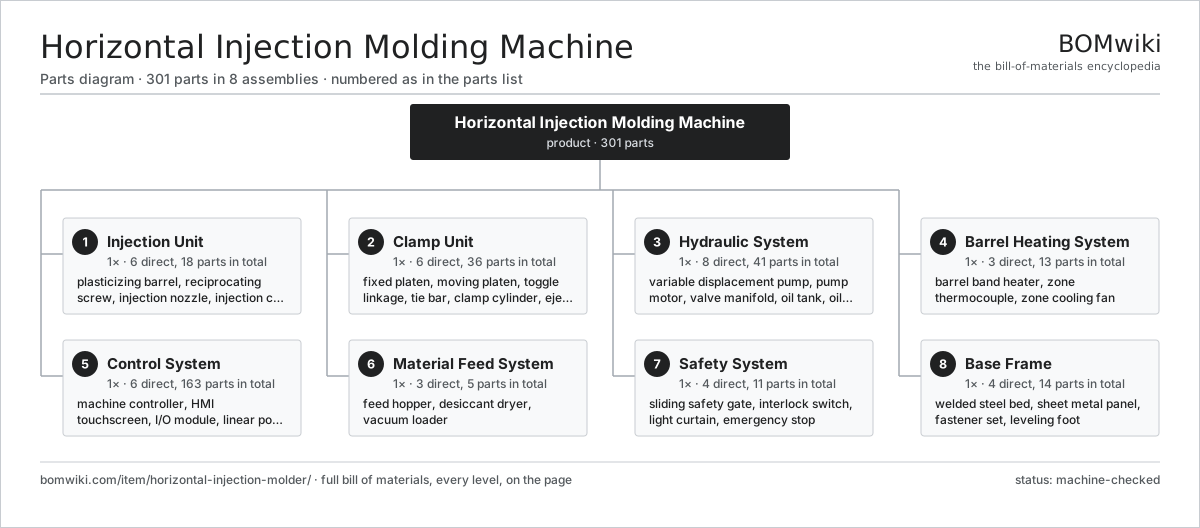
| # | Part | Qty | What it does |
|---|---|---|---|
| 1 | Injection Unit 6 parts | 1× | Reciprocating-screw barrel that melts, meters, and injects the plastic shot. |
| 2 | Clamp Unit 6 parts | 1× | Toggle clamp that holds the mold halves shut against injection pressure. |
| 3 | Hydraulic System 8 parts | 1× | Variable pump and valve manifold powering clamp, injection, and ejection. |
| 4 | Barrel Heating System 3 parts | 1× | Zoned band heaters and thermocouples that hold the melt profile. |
| 5 | Control System 6 parts | 1× | Machine controller closing pressure, position, and temperature loops. |
| 6 | Material Feed System 3 parts | 1× | Hopper, dryer, and loader supplying dry pellets to the feed throat. |
| 7 | Safety System 4 parts | 1× | Interlocked guards and switches that block clamp motion when open. |
| 8 | Base Frame 4 parts | 1× | Welded steel bed carrying clamp and injection units in line. |
3D model
No 3D model yet. Have a CAD file of this? Add a 3D model — STL renders right on this page; STEP, FreeCAD, and OpenSCAD sources are welcome too (openly licensed, like all 3D models on BOMwiki).
Build & assembly graph
expand / collapse · shared sub-assemblies converge · links to related products · est. labourTap an assembly to expand/collapse · tap a part to open it · use “Open page” for any node · drag to pan, scroll to zoom.
Bill of materials for Horizontal Injection Molding Machine
8 top-level lines · 88 rows shown · 301 parts total · indented to 3 levels| # | Item / sub-assembly | Part no. | Qty/assy | Ext. qty | Parts | Type |
|---|---|---|---|---|---|---|
| 1 | Injection Unit 6 parts | horizontal-injection-molder-injection-unit | 1× | 1 | 18 | assembly |
| 1.1 | Plasticizing Barrel 3 parts | horizontal-injection-molder-barrel | 1× | 1 | 3 | assembly |
| 1.1.1 | Barrel Tube | horizontal-injection-molder-barrel-tube | 1× | 1 | · | part |
| 1.1.2 | Bimetallic Liner | horizontal-injection-molder-barrel-liner | 1× | 1 | · | part |
| 1.1.3 | Water-Cooled Feed Throat | horizontal-injection-molder-feed-throat | 1× | 1 | · | part |
| 1.2 | Reciprocating Screw 3 parts | horizontal-injection-molder-screw | 1× | 1 | 3 | assembly |
| 1.2.1 | Screw Body | horizontal-injection-molder-screw-body | 1× | 1 | · | part |
| 1.2.2 | Non-Return Check Ring | horizontal-injection-molder-check-ring | 1× | 1 | · | part |
| 1.2.3 | Screw Tip | horizontal-injection-molder-screw-tip | 1× | 1 | · | part |
| 1.3 | Injection Nozzle 3 parts | horizontal-injection-molder-nozzle | 1× | 1 | 3 | assembly |
| 1.3.1 | Nozzle Body | horizontal-injection-molder-nozzle-body | 1× | 1 | · | part |
| 1.3.2 | Nozzle Tip | horizontal-injection-molder-nozzle-tip | 1× | 1 | · | part |
| 1.3.3 | Nozzle Band Heater 1 parts + deeper › | horizontal-injection-molder-nozzle-heater | 1× | 1 | · | part |
| 1.4 | Injection Cylinder | horizontal-injection-molder-injection-cylinder | 2× | 2 | · | part |
| 1.5 | Screw Rotation Drive 3 parts | horizontal-injection-molder-screw-drive | 1× | 1 | 4 | assembly |
| 1.5.1 | Hydraulic Motor | horizontal-injection-molder-hydraulic-motor | 1× | 1 | · | part |
| 1.5.2 | Helical Gear Pair | gear-pair | 1× | 1 | · | part |
| 1.5.3 | Ball Bearing | ball-bearing | 2× | 2 | · | part |
| 1.6 | Injection Carriage 2 parts | horizontal-injection-molder-carriage | 1× | 1 | 3 | assembly |
| 1.6.1 | Linear Guide Rail | linear-guide | 2× | 2 | · | part |
| 1.6.2 | Carriage Cylinder | horizontal-injection-molder-carriage-cylinder | 1× | 1 | · | part |
| 2 | Clamp Unit 6 parts | horizontal-injection-molder-clamp-unit | 1× | 1 | 36 | assembly |
| 2.1 | Fixed Platen | horizontal-injection-molder-fixed-platen | 1× | 1 | · | part |
| 2.2 | Moving Platen | horizontal-injection-molder-moving-platen | 1× | 1 | · | part |
| 2.3 | Toggle Linkage 3 parts | horizontal-injection-molder-toggle | 1× | 1 | 19 | assembly |
| 2.3.1 | Toggle Link | horizontal-injection-molder-toggle-link | 8× | 8 | · | part |
| 2.3.2 | Toggle Pin | horizontal-injection-molder-toggle-pin | 10× | 10 | · | part |
| 2.3.3 | Crosshead | horizontal-injection-molder-crosshead | 1× | 1 | · | part |
| 2.4 | Tie Bar | horizontal-injection-molder-tie-bar | 4× | 4 | · | part |
| 2.5 | Clamp Cylinder | horizontal-injection-molder-clamp-cylinder | 1× | 1 | · | part |
| 2.6 | Ejector System 3 parts | horizontal-injection-molder-ejector | 1× | 1 | 10 | assembly |
| 2.6.1 | Ejector Cylinder | horizontal-injection-molder-ejector-cylinder | 1× | 1 | · | part |
| 2.6.2 | Ejector Plate | horizontal-injection-molder-ejector-plate | 1× | 1 | · | part |
| 2.6.3 | Ejector Pin | horizontal-injection-molder-ejector-pin | 8× | 8 | · | part |
| 3 | Hydraulic System 8 parts | horizontal-injection-molder-hydraulic-system | 1× | 1 | 41 | assembly |
| 3.1 | Variable Displacement Pump | horizontal-injection-molder-pump | 1× | 1 | · | part |
| 3.2 | Pump Motor 2 parts | horizontal-injection-molder-pump-motor | 1× | 1 | · | part |
| 3.2.1 | Stator Assembly 3 parts + deeper › | stator-assembly | 1× | 1 | 3 | assembly |
| 3.2.2 | Rotor Assembly 4 parts + deeper › | rotor-assembly | 1× | 1 | 19 | assembly |
| 3.3 | Valve Manifold 3 parts | horizontal-injection-molder-valve-manifold | 1× | 1 | 10 | assembly |
| 3.3.1 | Proportional Valve | horizontal-injection-molder-proportional-valve | 3× | 3 | · | part |
| 3.3.2 | Directional Valve | horizontal-injection-molder-directional-valve | 6× | 6 | · | part |
| 3.3.3 | Manifold Block | horizontal-injection-molder-manifold-block | 1× | 1 | · | part |
| 3.4 | Oil Tank | horizontal-injection-molder-oil-tank | 1× | 1 | · | part |
| 3.5 | Oil Cooler | horizontal-injection-molder-oil-cooler | 1× | 1 | · | part |
| 3.6 | Accumulator | horizontal-injection-molder-accumulator | 1× | 1 | · | part |
| 3.7 | Pressure Sensor | pressure-sensor | 4× | 4 | · | part |
| 3.8 | O-Ring Set | oring-set | 1× | 1 | · | part |
| 4 | Barrel Heating System 3 parts | horizontal-injection-molder-heating-system | 1× | 1 | 13 | assembly |
| 4.1 | Barrel Band Heater 1 parts | horizontal-injection-molder-band-heater | 5× | 5 | · | part |
| 4.1.1 | Heating Element | heating-element | 1× | 5 | · | part |
| 4.2 | Zone Thermocouple | horizontal-injection-molder-thermocouple | 6× | 6 | · | part |
| 4.3 | Zone Cooling Fan | horizontal-injection-molder-cooling-fan | 2× | 2 | · | part |
| 5 | Control System 6 parts | horizontal-injection-molder-control-system | 1× | 1 | 163 | assembly |
| 5.1 | Machine Controller 4 parts | horizontal-injection-molder-controller | 1× | 1 | 130 | assembly |
| 5.1.1 | Bare PCB | pcb-bare | 1× | 1 | · | part |
| 5.1.2 | Microcontroller | mcu | 1× | 1 | · | part |
| 5.1.3 | SMD Passive (R/C/L) | smd-passives | 120× | 120 | · | part |
| 5.1.4 | Connector | connector | 8× | 8 | · | part |
| 5.2 | HMI Touchscreen 3 parts | horizontal-injection-molder-hmi | 1× | 1 | 3 | assembly |
| 5.2.1 | LCD Panel | lcd-panel | 1× | 1 | · | part |
| 5.2.2 | Bare PCB | pcb-bare | 1× | 1 | · | part |
| 5.2.3 | Microcontroller | mcu | 1× | 1 | · | part |
| 5.3 | I/O Module 3 parts | horizontal-injection-molder-io-module | 2× | 2 | 13 | assembly |
| 5.3.1 | Bare PCB | pcb-bare | 1× | 2 | · | part |
| 5.3.2 | Relay | relay | 8× | 16 | · | part |
| 5.3.3 | Connector | connector | 4× | 8 | · | part |
| 5.4 | Linear Position Sensor | horizontal-injection-molder-position-sensor | 2× | 2 | · | part |
| 5.5 | Wire Bundle | wire-bundle | 1× | 1 | · | part |
| 5.6 | Power Supply | power-supply | 1× | 1 | · | part |
| 6 | Material Feed System 3 parts | horizontal-injection-molder-feed-system | 1× | 1 | 5 | assembly |
| 6.1 | Feed Hopper | horizontal-injection-molder-hopper | 1× | 1 | · | part |
| 6.2 | Desiccant Dryer 3 parts | horizontal-injection-molder-dryer | 1× | 1 | 3 | assembly |
| 6.2.1 | Heating Element | heating-element | 1× | 1 | · | part |
| 6.2.2 | Desiccant Bed | horizontal-injection-molder-desiccant-bed | 1× | 1 | · | part |
| 6.2.3 | Drying Blower | horizontal-injection-molder-blower | 1× | 1 | · | part |
| 6.3 | Vacuum Loader | horizontal-injection-molder-loader | 1× | 1 | · | part |
| 7 | Safety System 4 parts | horizontal-injection-molder-safety-system | 1× | 1 | 11 | assembly |
| 7.1 | Sliding Safety Gate 1 parts | horizontal-injection-molder-safety-gate | 2× | 2 | · | part |
| 7.1.1 | Sheet Metal Panel | sheet-panel | 2× | 4 | · | part |
| 7.2 | Interlock Switch | horizontal-injection-molder-safety-switch | 4× | 4 | · | part |
| 7.3 | Light Curtain | horizontal-injection-molder-light-curtain | 1× | 1 | · | part |
| 7.4 | Emergency Stop | horizontal-injection-molder-estop | 2× | 2 | · | part |
| 8 | Base Frame 4 parts | horizontal-injection-molder-base-frame | 1× | 1 | 14 | assembly |
| 8.1 | Welded Steel Bed | horizontal-injection-molder-bed | 1× | 1 | · | part |
| 8.2 | Sheet Metal Panel | sheet-panel | 6× | 6 | · | part |
| 8.3 | Fastener Set | fastener-set | 1× | 1 | · | part |
| 8.4 | Leveling Foot | horizontal-injection-molder-leveling-foot | 6× | 6 | · | part |
Related products
same domain, ranked by shared parts Rubber Extrusion Line
524 parts · shares 20 with this page
Rubber Extrusion Line
524 parts · shares 20 with this page
 Investment Casting Shell Line
869 parts · shares 20 with this page
Powder Coating Line
5,418 parts · shares 20 with this page
Investment Casting Shell Line
869 parts · shares 20 with this page
Powder Coating Line
5,418 parts · shares 20 with this page
 Continuous Galvanizing Line
1,296 parts · shares 19 with this page
Continuous Galvanizing Line
1,296 parts · shares 19 with this page
Sourcing: possible vendors
Prices, MOQ, and lead times are algorithmic estimates, not quotes, and not claims about these companies. Company mappings are curated by keyword; est. price band $5k–$2M. How estimates work| Vendor | HQ | Specialty | MOQ | Lead time |
|---|---|---|---|---|
| atlascopco.com ↗ | Stockholm, SE | Compressors & industrial | 10 units | 12–20 wks |
|
🇦🇹Andritz
andritz.com ↗
|
Graz, AT | Process plants & machinery | 10 units | 12–20 wks |
| buhlergroup.com ↗ | Uzwil, CH | Food & materials processing | 10 units | 12–20 wks |
| gea.com ↗ | Düsseldorf, DE | Process technology | 10 units | 12–20 wks |
| mhi.com ↗ | Tokyo, JP | Heavy machinery | 10 units | 12–20 wks |
978-word article