Rubber Extrusion Line
ProductOverview
A rubber extrusion line turns a mixed rubber compound into a continuous profile of constant cross-section: door and window seals, automotive weatherstrip, sponge and dense profiles, garden and industrial hose, and cord. Unlike injection or compression molding, which make discrete parts, extrusion runs without stopping, so the economics favor long lengths of the same section. The Cold-Feed Extruder shapes the compound and pushes it through a Die Head, then a sequence of downstream machines cures the soft profile, cools it, pulls it through at a set speed and cuts or coils it.
Rubber extrusion differs from plastic extrusion in one decisive way: the compound must not vulcanize inside the barrel. The screw and barrel run warm enough to make the rubber flow but cool enough to keep it un-cured, and cross-linking only happens later in the curing oven. That single constraint shapes the whole line.
The extruder
Modern lines use a cold-feed Cold-Feed Extruder: pre-warmed rubber strip from a mill enters the Feed Throat, where a driven Feed Roller forces it onto the screw. The Single Screw has deep feed flights and a shallower metering section, so it conveys, works and pressurizes the compound as it turns. A Screw Tip sets the gap to the breaker plate.
Temperature control is split along the Barrel into zones. Each Barrel Temperature Zone carries band or cartridge Heating Element units and an RTD, and each is paired with a Cooling Water Jacket carrying water. The dual heat-and-cool arrangement matters because the screw itself generates shear heat. Without active cooling the compound would climb past its scorch temperature and begin to cure in the barrel, which would scrap the run and clog the head. A Screw Thrust Bearing takes the large axial load the screw develops against the die back-pressure.
Drive
The screw turns slowly with very high torque, so the Main Drive uses a Main Motor feeding a multi-stage Reduction Gearbox of helical Helical Gear Pair stages in a Gearbox Housing. A Drive Coupling links the gearbox to the screw. Screw speed sets output, and on a synchronized line the control trims it against haul-off speed to hold the profile dimensions steady.
Die head and tooling
The Die Head is where the section is formed. A Breaker Plate straightens the rotating flow and supports a Screen Pack that filters contaminants and raises back-pressure for better mixing. The Extrusion Die is the shaped orifice, and for tube and hose a Die Insert with a mandrel pin sets the bore. Rubber swells and relaxes after the die, so the die opening is not the same shape as the finished profile; die design compensates for that die swell and for draw-down in the haul-off. A Head Melt-Pressure Sensor watches head pressure to flag a blinded screen.
Curing and cooling
The profile leaves the die soft and un-cured. The UHF / Hot-Air Curing Oven is a vulcanization tunnel that cross-links the rubber on the move. UHF lines use a UHF Generator with a Magnetron feeding a UHF Applicator; microwaves heat the rubber volumetrically from the inside, which is far faster and more even than surface heating, then Hot-Air Zone sections hold the cure temperature to finish vulcanization. A PTFE-coated Tunnel Conveyor carries the soft profile without marking it. Salt-bath and pure hot-air tunnels are the older alternatives. After cure the Cooling Trough runs the profile through water to set its dimensions, followed by an Air Wipe.
Downstream line
A twin-belt Haul-Off Caterpillar draws the profile through the whole line at a controlled speed; the ratio of haul-off speed to extruder output sets the draw-down and thus the final size. A Cut-Off Station station cuts strip and gasket lengths with a Guillotine triggered by a Length Counter, while hose and cord run to a Take-Up / Coiler coiler with a Traverse Guide for even winding. Because freshly cured rubber is tacky, a Talc Dusting Station station coats it with talc so it does not stick to itself in the coil.
Control, use and maintenance
The Control Cabinet cabinet holds the PLC, a HMI Panel, VFD Drive drives and a Zone Temperature Controller per zone, coordinating screw speed, temperatures, line speed and cut length so the line runs as one process. Common problems are scorch from lost barrel cooling, surface porosity from poor degassing in the Vacuum Feed Hopper, and dimensional drift when haul-off and extruder fall out of sync. Maintenance focuses on screw and barrel wear from filled compounds, die cleaning and polishing, screen-pack changes, and keeping the cooling water and vacuum systems working.
Rubber Extrusion Line parts and their functions
12 top-level parts · 524 parts in total · full bill of materials below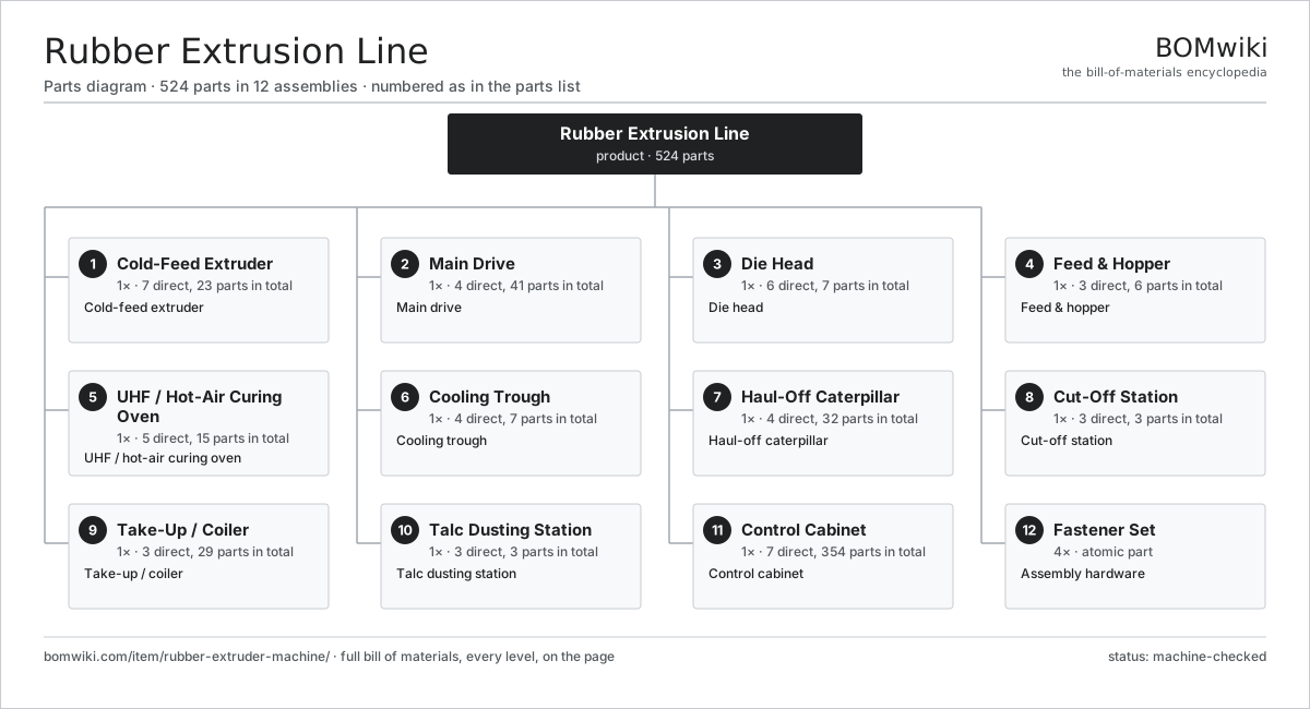
| # | Part | Qty | What it does |
|---|---|---|---|
| 1 | Cold-Feed Extruder 7 parts | 1× | Cold-feed extruder |
| 2 | Main Drive 4 parts | 1× | Main drive |
| 3 | Die Head 6 parts | 1× | Die head |
| 4 | Feed & Hopper 3 parts | 1× | Feed & hopper |
| 5 | UHF / Hot-Air Curing Oven 5 parts | 1× | UHF / hot-air curing oven |
| 6 | Cooling Trough 4 parts | 1× | Cooling trough |
| 7 | Haul-Off Caterpillar 4 parts | 1× | Haul-off caterpillar |
| 8 | Cut-Off Station 3 parts | 1× | Cut-off station |
| 9 | Take-Up / Coiler 3 parts | 1× | Take-up / coiler |
| 10 | Talc Dusting Station 3 parts | 1× | Talc dusting station |
| 11 | Control Cabinet 7 parts | 1× | Control cabinet |
| 12 | Fastener Set | 4× | Assembly hardware |
3D model
No 3D model yet. Have a CAD file of this? Add a 3D model — STL renders right on this page; STEP, FreeCAD, and OpenSCAD sources are welcome too (openly licensed, like all 3D models on BOMwiki).
Build & assembly graph
expand / collapse · shared sub-assemblies converge · links to related products · est. labourTap an assembly to expand/collapse · tap a part to open it · use “Open page” for any node · drag to pan, scroll to zoom.
Bill of materials for Rubber Extrusion Line
12 top-level lines · 111 rows shown · 524 parts total · indented to 3 levels| # | Item / sub-assembly | Part no. | Qty/assy | Ext. qty | Parts | Type |
|---|---|---|---|---|---|---|
| 1 | Cold-Feed Extruder 7 parts | rubber-extruder-machine-extruder | 1× | 1 | 23 | assembly |
| 1.1 | Barrel | rubber-extruder-machine-barrel | 1× | 1 | · | part |
| 1.2 | Single Screw | rubber-extruder-machine-screw | 1× | 1 | · | part |
| 1.3 | Screw Tip | rubber-extruder-machine-screw-tip | 1× | 1 | · | part |
| 1.4 | Feed Throat 1 parts | rubber-extruder-machine-feed-throat | 1× | 1 | · | part |
| 1.4.1 | Feed Roller | rubber-extruder-machine-feed-roller | 1× | 1 | · | part |
| 1.5 | Barrel Temperature Zone 2 parts | rubber-extruder-machine-temp-zone | 4× | 4 | · | part |
| 1.5.1 | Heating Element | heating-element | 2× | 8 | · | part |
| 1.5.2 | Zone RTD | rubber-extruder-machine-rtd | 1× | 4 | · | part |
| 1.6 | Cooling Water Jacket | rubber-extruder-machine-cooling-jacket | 4× | 4 | · | part |
| 1.7 | Screw Thrust Bearing 2 parts | rubber-extruder-machine-thrust-bearing | 1× | 1 | · | part |
| 1.7.1 | Ball Bearing | ball-bearing | 2× | 2 | · | part |
| 1.7.2 | Oil Seal | oil-seal | 1× | 1 | · | part |
| 2 | Main Drive 4 parts | rubber-extruder-machine-drive | 1× | 1 | 41 | assembly |
| 2.1 | Main Motor 5 parts | rubber-extruder-machine-main-motor | 1× | 1 | 26 | assembly |
| 2.1.1 | Stator Assembly 3 parts + deeper › | stator-assembly | 1× | 1 | 3 | assembly |
| 2.1.2 | Rotor Assembly 4 parts + deeper › | rotor-assembly | 1× | 1 | 19 | assembly |
| 2.1.3 | Motor Housing | motor-housing | 1× | 1 | · | part |
| 2.1.4 | Ball Bearing | ball-bearing | 2× | 2 | · | part |
| 2.1.5 | Oil Seal | oil-seal | 1× | 1 | · | part |
| 2.2 | Reduction Gearbox 4 parts | rubber-extruder-machine-gearbox | 1× | 1 | 13 | assembly |
| 2.2.1 | Helical Gear Pair | gear-pair | 3× | 3 | · | part |
| 2.2.2 | Gearbox Housing | gearbox-housing | 1× | 1 | · | part |
| 2.2.3 | Ball Bearing | ball-bearing | 6× | 6 | · | part |
| 2.2.4 | Oil Seal | oil-seal | 3× | 3 | · | part |
| 2.3 | Drive Belt | drive-belt | 1× | 1 | · | part |
| 2.4 | Drive Coupling | rubber-extruder-machine-coupling | 1× | 1 | · | part |
| 3 | Die Head 6 parts | rubber-extruder-machine-die-head | 1× | 1 | 7 | assembly |
| 3.1 | Breaker Plate | rubber-extruder-machine-breaker-plate | 1× | 1 | · | part |
| 3.2 | Screen Pack | rubber-extruder-machine-screen-pack | 1× | 1 | · | part |
| 3.3 | Extrusion Die | rubber-extruder-machine-extrusion-die | 1× | 1 | · | part |
| 3.4 | Die Insert | rubber-extruder-machine-die-insert | 1× | 1 | · | part |
| 3.5 | Head Heater 1 parts | rubber-extruder-machine-head-heater | 2× | 2 | · | part |
| 3.5.1 | Heating Element | heating-element | 1× | 2 | · | part |
| 3.6 | Head Melt-Pressure Sensor 1 parts | rubber-extruder-machine-pressure-sensor | 1× | 1 | · | part |
| 3.6.1 | Pressure Sensor | pressure-sensor | 1× | 1 | · | part |
| 4 | Feed & Hopper 3 parts | rubber-extruder-machine-feed | 1× | 1 | 6 | assembly |
| 4.1 | Strip Feed Conveyor 1 parts | rubber-extruder-machine-feed-conveyor | 1× | 1 | · | part |
| 4.1.1 | Drive Belt | drive-belt | 1× | 1 | · | part |
| 4.2 | Vacuum Feed Hopper 1 parts | rubber-extruder-machine-vacuum-hopper | 1× | 1 | · | part |
| 4.2.1 | O-Ring Set | oring-set | 2× | 2 | · | part |
| 4.3 | Vacuum Pump 2 parts | rubber-extruder-machine-vacuum-pump | 1× | 1 | · | part |
| 4.3.1 | Ball Bearing | ball-bearing | 2× | 2 | · | part |
| 4.3.2 | Oil Seal | oil-seal | 1× | 1 | · | part |
| 5 | UHF / Hot-Air Curing Oven 5 parts | rubber-extruder-machine-curing-oven | 1× | 1 | 15 | assembly |
| 5.1 | UHF Generator 3 parts | rubber-extruder-machine-uhf-generator | 1× | 1 | 3 | assembly |
| 5.1.1 | Magnetron | rubber-extruder-machine-magnetron | 1× | 1 | · | part |
| 5.1.2 | Power Supply | power-supply | 1× | 1 | · | part |
| 5.1.3 | Waveguide | rubber-extruder-machine-waveguide | 1× | 1 | · | part |
| 5.2 | UHF Applicator | rubber-extruder-machine-uhf-applicator | 1× | 1 | · | part |
| 5.3 | Hot-Air Zone 2 parts | rubber-extruder-machine-hot-air-zone | 3× | 3 | · | part |
| 5.3.1 | Heating Element | heating-element | 2× | 6 | · | part |
| 5.3.2 | Circulation Fan | rubber-extruder-machine-circulation-fan | 1× | 3 | · | part |
| 5.4 | Tunnel Conveyor 1 parts | rubber-extruder-machine-oven-conveyor | 1× | 1 | · | part |
| 5.4.1 | Drive Belt | drive-belt | 1× | 1 | · | part |
| 5.5 | Fume Exhaust Fan | rubber-extruder-machine-exhaust-fan | 1× | 1 | · | part |
| 6 | Cooling Trough 4 parts | rubber-extruder-machine-cooling-trough | 1× | 1 | 7 | assembly |
| 6.1 | Water Tank | rubber-extruder-machine-water-tank | 1× | 1 | · | part |
| 6.2 | Recirculation Pump 2 parts | rubber-extruder-machine-water-pump | 1× | 1 | · | part |
| 6.2.1 | Ball Bearing | ball-bearing | 2× | 2 | · | part |
| 6.2.2 | Oil Seal | oil-seal | 1× | 1 | · | part |
| 6.3 | Spray Bar | rubber-extruder-machine-spray-bar | 2× | 2 | · | part |
| 6.4 | Air Wipe | rubber-extruder-machine-air-wipe | 1× | 1 | · | part |
| 7 | Haul-Off Caterpillar 4 parts | rubber-extruder-machine-haul-off | 1× | 1 | 32 | assembly |
| 7.1 | Caterpillar Belt 1 parts | rubber-extruder-machine-caterpillar-belt | 2× | 2 | · | part |
| 7.1.1 | Drive Belt | drive-belt | 1× | 2 | · | part |
| 7.2 | Haul-Off Motor 3 parts | rubber-extruder-machine-haul-motor | 1× | 1 | 27 | assembly |
| 7.2.1 | Servo Motor 4 parts + deeper › | servo-motor | 1× | 1 | 24 | assembly |
| 7.2.2 | Helical Gear Pair | gear-pair | 1× | 1 | · | part |
| 7.2.3 | Ball Bearing | ball-bearing | 2× | 2 | · | part |
| 7.3 | Belt Tensioner 1 parts | rubber-extruder-machine-belt-tensioner | 2× | 2 | · | part |
| 7.3.1 | Coil Spring | coil-spring | 1× | 2 | · | part |
| 7.4 | Line-Speed Encoder | rubber-extruder-machine-encoder | 1× | 1 | · | part |
| 8 | Cut-Off Station 3 parts | rubber-extruder-machine-cutoff | 1× | 1 | 3 | assembly |
| 8.1 | Guillotine 1 parts | rubber-extruder-machine-guillotine | 1× | 1 | · | part |
| 8.1.1 | Cut Cylinder 1 parts + deeper › | rubber-extruder-machine-cut-cylinder | 1× | 1 | · | part |
| 8.2 | Cut Blade | rubber-extruder-machine-cut-blade | 1× | 1 | · | part |
| 8.3 | Length Counter | rubber-extruder-machine-length-counter | 1× | 1 | · | part |
| 9 | Take-Up / Coiler 3 parts | rubber-extruder-machine-takeup | 1× | 1 | 29 | assembly |
| 9.1 | Coiler Reel 1 parts | rubber-extruder-machine-coiler-reel | 1× | 1 | · | part |
| 9.1.1 | Ball Bearing | ball-bearing | 2× | 2 | · | part |
| 9.2 | Coiler Motor 2 parts | rubber-extruder-machine-coiler-motor | 1× | 1 | 25 | assembly |
| 9.2.1 | Servo Motor 4 parts + deeper › | servo-motor | 1× | 1 | 24 | assembly |
| 9.2.2 | Helical Gear Pair | gear-pair | 1× | 1 | · | part |
| 9.3 | Traverse Guide 2 parts | rubber-extruder-machine-traverse | 1× | 1 | · | part |
| 9.3.1 | Ball Screw | ball-screw | 1× | 1 | · | part |
| 9.3.2 | Linear Guide Rail | linear-guide | 1× | 1 | · | part |
| 10 | Talc Dusting Station 3 parts | rubber-extruder-machine-dusting | 1× | 1 | 3 | assembly |
| 10.1 | Dusting Chamber | rubber-extruder-machine-dust-chamber | 1× | 1 | · | part |
| 10.2 | Talc Blower | rubber-extruder-machine-dust-blower | 1× | 1 | · | part |
| 10.3 | Dust Collector | rubber-extruder-machine-dust-collector | 1× | 1 | · | part |
| 11 | Control Cabinet 7 parts | rubber-extruder-machine-control | 1× | 1 | 354 | assembly |
| 11.1 | PLC 4 parts | rubber-extruder-machine-plc | 1× | 1 | 160 | assembly |
| 11.1.1 | Bare PCB | pcb-bare | 1× | 1 | · | part |
| 11.1.2 | Microcontroller | mcu | 1× | 1 | · | part |
| 11.1.3 | Relay | relay | 8× | 8 | · | part |
| 11.1.4 | SMD Passive (R/C/L) | smd-passives | 150× | 150 | · | part |
| 11.2 | HMI Panel 3 parts | rubber-extruder-machine-hmi | 1× | 1 | 42 | assembly |
| 11.2.1 | Bare PCB | pcb-bare | 1× | 1 | · | part |
| 11.2.2 | LCD Panel | lcd-panel | 1× | 1 | · | part |
| 11.2.3 | SMD Passive (R/C/L) | smd-passives | 40× | 40 | · | part |
| 11.3 | VFD Drive 2 parts | rubber-extruder-machine-vfd | 2× | 2 | · | part |
| 11.3.1 | Bare PCB | pcb-bare | 1× | 2 | · | part |
| 11.3.2 | SMD Passive (R/C/L) | smd-passives | 60× | 120 | · | part |
| 11.4 | Zone Temperature Controller 2 parts | rubber-extruder-machine-temp-controller | 4× | 4 | · | part |
| 11.4.1 | Bare PCB | pcb-bare | 1× | 4 | · | part |
| 11.4.2 | Relay | relay | 2× | 8 | · | part |
| 11.5 | Power Supply | power-supply | 1× | 1 | · | part |
| 11.6 | Wire Bundle | wire-bundle | 1× | 1 | · | part |
| 11.7 | Connector | connector | 16× | 16 | · | part |
| 12 | Fastener Set | fastener-set | 4× | 4 | · | part |
Related products
same domain, ranked by shared parts Continuous Galvanizing Line
1,296 parts · shares 25 with this page
Continuous Galvanizing Line
1,296 parts · shares 25 with this page
 Tensile Testing Machine
608 parts · shares 22 with this page
Hammer Mill
790 parts · shares 23 with this page
Tensile Testing Machine
608 parts · shares 22 with this page
Hammer Mill
790 parts · shares 23 with this page
Sourcing: possible vendors
Prices, MOQ, and lead times are algorithmic estimates, not quotes, and not claims about these companies. Company mappings are curated by keyword; est. price band $5k–$2M. How estimates work| Vendor | HQ | Specialty | MOQ | Lead time |
|---|---|---|---|---|
| atlascopco.com ↗ | Stockholm, SE | Compressors & industrial | 10 units | 12–20 wks |
|
🇦🇹Andritz
andritz.com ↗
|
Graz, AT | Process plants & machinery | 10 units | 12–20 wks |
| buhlergroup.com ↗ | Uzwil, CH | Food & materials processing | 10 units | 12–20 wks |
| gea.com ↗ | Düsseldorf, DE | Process technology | 10 units | 12–20 wks |
| mhi.com ↗ | Tokyo, JP | Heavy machinery | 10 units | 12–20 wks |
882-word article