O-Ring Molding Press
ProductOverview
An O-ring molding press makes sealing rings by squeezing a measured charge of uncured rubber between two heated mold halves and holding it under pressure until the rubber cross-links into a finished elastic ring. Compression molding suits O-rings well because the part is small, the cross section is simple, and one mold can carry dozens or hundreds of cavities, so a single press shot yields a sheet of rings. The press provides three things the chemistry needs: high clamp force to keep the mold closed against the internal pressure of the curing rubber, steady heat to drive the cure, and an accurate timer so every ring sees the same cure.
The machine builds force through the Press Frame and the Hydraulic System system, forms the part in the O-Ring Mold, holds temperature with the Heating System system, loads rubber with the Preform Feed Station station, cleans the rings in the Deflash Unit unit, and runs the cycle from the Press Controller.
Frame and clamp
The Press Frame carries the entire clamp load. A welded Base Frame holds the lower Fixed Platen, and four hardened Tie Bar columns link it to the upper Moving Platen, which slides on a set of Linear Guide Rail rails so the mold faces stay parallel. When the Hydraulic System system pressurizes the Clamp Ram, the Ram Piston drives the moving platen down and clamps the mold with tens to over a hundred tonnes of force. That force has to exceed the pressure the rubber generates as it heats and expands, or the mold opens slightly and the ring grows flash and loses dimension. A motor-driven Hydraulic Pump feeds the Valve Manifold, where a Directional Valve sets ram direction and a Relief Valve caps pressure. Two Pressure Sensor units let the controller hold a target tonnage through the cure.
The mold
The O-Ring Mold is where the ring takes shape. A Top Mold Plate and a Bottom Mold Plate sandwich a set of Cavity Insert pieces, each ground with a half-round groove that, when the mold closes, forms the round cross section and the inside and outside diameters of one O-ring. Running many inserts in one mold is how a press reaches hundreds of rings per shot. A set of Guide Pin columns aligns the halves so the parting line falls exactly on the ring centerline, because an offset parting line leaves a step that ruins the seal. After cure the Ejector lifts the molded web of rings clear so the next charge can load. Mold steel is hardened and often chrome-plated, since the rubber compounds are abrasive and the mold must hold dimension over long runs.
Heat and cure
Rubber cures by heat, so the Heating System system holds the platens at the compound's cure temperature, commonly 160 to 200 C. Banks of Heating Element cartridges sit in drilled bores in each platen, and a set of Thermocouple sensors feed the temperature loops. A Insulation Board between platen and frame keeps that heat in the tooling rather than leaking into the press, which saves energy and keeps the structure dimensionally stable. Fast Solid-State Relay relays switch the heaters so the controller holds each platen within a couple of degrees, which matters because cure time depends sharply on temperature and an uneven platen leaves some rings undercured. The cure timer is the other half: too short and the ring is soft and takes a compression set, too long and it can revert or scorch.
Feeding and deflashing
The Preform Feed Station station places the rubber charge. A Preform Tray presents weighed Rubber Preform slugs or extruded ribbon, and a Loader Arm driven by a Servo Motor drops one charge into each cavity before the press closes. Getting the charge weight right matters: too little starves the cavity, too much forces excess rubber out as flash. After cure, every ring carries a thin film of flash at the parting line, and the Deflash Unit unit removes it. The molded rings tumble in the Tumbling Drum while a Nitrogen Nozzle sprays liquid nitrogen to chill them below their glass transition, which makes the thin flash brittle while the ring body stays tough. A Media Blast Wheel wheel then throws polymer media that snaps the frozen flash off cleanly.
Control and use
The Press Controller cabinet runs the whole sequence. A Microcontroller on the controller board steps through load, clamp, cure timing, and ejection, drives the heater loops, and reads the Operator Touchscreen where the operator selects a stored recipe for the compound and ring size. A Power Supply feeds the cabinet, a bank of Relay outputs switches the station motors and valves, and a Wire Bundle with field Connector blocks carries signals to the press. O-ring molding presses run in seal plants making rings for hydraulics, automotive, plumbing, and aerospace, where consistent cure and tight cross-section control decide whether the ring seals over its rated pressure and temperature. Compound choice drives much of the setup: NBR for oil, FKM for fuel and heat, EPDM for water and steam, and silicone for wide temperature service, each with its own cure schedule the press holds shot after shot.
O-Ring Molding Press parts and their functions
7 top-level parts · 166 parts in total · full bill of materials below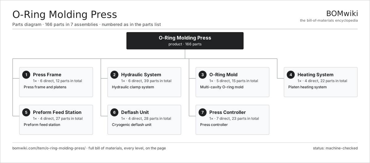
| # | Part | Qty | What it does |
|---|---|---|---|
| 1 | Press Frame 6 parts | 1× | Press frame and platens |
| 2 | Hydraulic System 6 parts | 1× | Hydraulic clamp system |
| 3 | O-Ring Mold 5 parts | 1× | Multi-cavity O-ring mold |
| 4 | Heating System 4 parts | 1× | Platen heating system |
| 5 | Preform Feed Station 4 parts | 1× | Preform feed station |
| 6 | Deflash Unit 4 parts | 1× | Cryogenic deflash unit |
| 7 | Press Controller 7 parts | 1× | Press controller |
3D model
No 3D model yet. Have a CAD file of this? Add a 3D model — STL renders right on this page; STEP, FreeCAD, and OpenSCAD sources are welcome too (openly licensed, like all 3D models on BOMwiki).
Build & assembly graph
expand / collapse · shared sub-assemblies converge · links to related products · est. labourTap an assembly to expand/collapse · tap a part to open it · use “Open page” for any node · drag to pan, scroll to zoom.
Bill of materials for O-Ring Molding Press
7 top-level lines · 58 rows shown · 166 parts total · indented to 3 levels| # | Item / sub-assembly | Part no. | Qty/assy | Ext. qty | Parts | Type |
|---|---|---|---|---|---|---|
| 1 | Press Frame 6 parts | o-ring-molding-press-frame | 1× | 1 | 12 | assembly |
| 1.1 | Base Frame | o-ring-molding-press-base-frame | 1× | 1 | · | part |
| 1.2 | Fixed Platen | o-ring-molding-press-fixed-platen | 1× | 1 | · | part |
| 1.3 | Moving Platen | o-ring-molding-press-moving-platen | 1× | 1 | · | part |
| 1.4 | Tie Bar | o-ring-molding-press-tie-bar | 4× | 4 | · | part |
| 1.5 | Linear Guide Rail | linear-guide | 4× | 4 | · | part |
| 1.6 | Fastener Set | fastener-set | 1× | 1 | · | part |
| 2 | Hydraulic System 6 parts | o-ring-molding-press-hydraulic | 1× | 1 | 39 | assembly |
| 2.1 | Clamp Ram 3 parts | o-ring-molding-press-ram | 1× | 1 | 4 | assembly |
| 2.1.1 | Ram Cylinder | o-ring-molding-press-cylinder | 1× | 1 | · | part |
| 2.1.2 | Ram Piston | o-ring-molding-press-piston | 1× | 1 | · | part |
| 2.1.3 | Oil Seal | oil-seal | 2× | 2 | · | part |
| 2.2 | Hydraulic Pump 2 parts | o-ring-molding-press-pump | 1× | 1 | 25 | assembly |
| 2.2.1 | Servo Motor 4 parts + deeper › | servo-motor | 1× | 1 | 24 | assembly |
| 2.2.2 | Gear Pump | o-ring-molding-press-gear-pump | 1× | 1 | · | part |
| 2.3 | Oil Reservoir | o-ring-molding-press-tank | 1× | 1 | · | part |
| 2.4 | Valve Manifold 2 parts | o-ring-molding-press-valve-block | 1× | 1 | 3 | assembly |
| 2.4.1 | Directional Valve | o-ring-molding-press-directional-valve | 2× | 2 | · | part |
| 2.4.2 | Relief Valve | o-ring-molding-press-relief-valve | 1× | 1 | · | part |
| 2.5 | Pressure Sensor | pressure-sensor | 2× | 2 | · | part |
| 2.6 | O-Ring Set | oring-set | 4× | 4 | · | part |
| 3 | O-Ring Mold 5 parts | o-ring-molding-press-mold | 1× | 1 | 15 | assembly |
| 3.1 | Top Mold Plate | o-ring-molding-press-top-plate | 1× | 1 | · | part |
| 3.2 | Bottom Mold Plate | o-ring-molding-press-bottom-plate | 1× | 1 | · | part |
| 3.3 | Cavity Insert | o-ring-molding-press-cavity-insert | 8× | 8 | · | part |
| 3.4 | Guide Pin | o-ring-molding-press-guide-pin | 4× | 4 | · | part |
| 3.5 | Ejector | o-ring-molding-press-ejector | 1× | 1 | · | part |
| 4 | Heating System 4 parts | o-ring-molding-press-heating | 1× | 1 | 22 | assembly |
| 4.1 | Heating Element | heating-element | 12× | 12 | · | part |
| 4.2 | Thermocouple | o-ring-molding-press-thermocouple | 4× | 4 | · | part |
| 4.3 | Insulation Board | o-ring-molding-press-insulation-board | 2× | 2 | · | part |
| 4.4 | Solid-State Relay | o-ring-molding-press-ssr | 4× | 4 | · | part |
| 5 | Preform Feed Station 4 parts | o-ring-molding-press-feed | 1× | 1 | 27 | assembly |
| 5.1 | Preform Tray | o-ring-molding-press-preform-tray | 1× | 1 | · | part |
| 5.2 | Loader Arm | o-ring-molding-press-loader-arm | 1× | 1 | · | part |
| 5.3 | Servo Motor 4 parts | servo-motor | 1× | 1 | 24 | assembly |
| 5.3.1 | Stator Assembly 3 parts + deeper › | stator-assembly | 1× | 1 | 3 | assembly |
| 5.3.2 | Rotor Assembly 4 parts + deeper › | rotor-assembly | 1× | 1 | 19 | assembly |
| 5.3.3 | Encoder | encoder | 1× | 1 | · | part |
| 5.3.4 | Motor Housing | motor-housing | 1× | 1 | · | part |
| 5.4 | Rubber Preform | o-ring-molding-press-preform | 1× | 1 | · | part |
| 6 | Deflash Unit 4 parts | o-ring-molding-press-deflash | 1× | 1 | 28 | assembly |
| 6.1 | Tumbling Drum | o-ring-molding-press-deflash-drum | 1× | 1 | · | part |
| 6.2 | Nitrogen Nozzle | o-ring-molding-press-nitrogen-nozzle | 2× | 2 | · | part |
| 6.3 | Media Blast Wheel | o-ring-molding-press-media-blast | 1× | 1 | · | part |
| 6.4 | Servo Motor 4 parts | servo-motor | 1× | 1 | 24 | assembly |
| 6.4.1 | Stator Assembly 3 parts + deeper › | stator-assembly | 1× | 1 | 3 | assembly |
| 6.4.2 | Rotor Assembly 4 parts + deeper › | rotor-assembly | 1× | 1 | 19 | assembly |
| 6.4.3 | Encoder | encoder | 1× | 1 | · | part |
| 6.4.4 | Motor Housing | motor-housing | 1× | 1 | · | part |
| 7 | Press Controller 7 parts | o-ring-molding-press-control | 1× | 1 | 23 | assembly |
| 7.1 | Bare PCB | pcb-bare | 1× | 1 | · | part |
| 7.2 | Microcontroller | mcu | 1× | 1 | · | part |
| 7.3 | Operator Touchscreen | o-ring-molding-press-hmi | 1× | 1 | · | part |
| 7.4 | Power Supply | power-supply | 1× | 1 | · | part |
| 7.5 | Relay | relay | 6× | 6 | · | part |
| 7.6 | Connector | connector | 12× | 12 | · | part |
| 7.7 | Wire Bundle | wire-bundle | 1× | 1 | · | part |
Related products
same domain, ranked by shared parts Rubber Extrusion Line
524 parts · shares 21 with this page
Rubber Extrusion Line
524 parts · shares 21 with this page
 Continuous Galvanizing Line
1,296 parts · shares 20 with this page
Powder Coating Line
5,418 parts · shares 20 with this page
Continuous Galvanizing Line
1,296 parts · shares 20 with this page
Powder Coating Line
5,418 parts · shares 20 with this page
 Industrial Ultrasonic Cleaner
787 parts · shares 20 with this page
Micro Injection Molding Machine
704 parts · shares 20 with this page
Industrial Ultrasonic Cleaner
787 parts · shares 20 with this page
Micro Injection Molding Machine
704 parts · shares 20 with this page
Sourcing: possible vendors
Prices, MOQ, and lead times are algorithmic estimates, not quotes, and not claims about these companies. Company mappings are curated by keyword; est. price band $5k–$2M. How estimates work| Vendor | HQ | Specialty | MOQ | Lead time |
|---|---|---|---|---|
| atlascopco.com ↗ | Stockholm, SE | Compressors & industrial | 10 units | 12–20 wks |
|
🇦🇹Andritz
andritz.com ↗
|
Graz, AT | Process plants & machinery | 10 units | 12–20 wks |
| buhlergroup.com ↗ | Uzwil, CH | Food & materials processing | 10 units | 12–20 wks |
| gea.com ↗ | Düsseldorf, DE | Process technology | 10 units | 12–20 wks |
| mhi.com ↗ | Tokyo, JP | Heavy machinery | 10 units | 12–20 wks |
999-word article