Thermal Spray Coating System
ProductOverview
A thermal spray coating system builds a protective layer on a part by melting a feedstock, usually a powder, and throwing the molten droplets at the surface, where they flatten, freeze, and stack into a coating. In the plasma version described here, a DC arc heats a flowing gas to roughly 15000 K, hot enough to melt almost any metal, ceramic, or carbide. The droplets hit the part at a few hundred metres per second, splat into thin lamellae, and cool in microseconds, so the coating grows splat by splat into a dense layer that resists wear, heat, or corrosion far better than the bare substrate.
The system is built around a small set of jobs: making the hot jet, feeding powder into it, supplying clean gas and power, cooling the gun, moving everything, and containing the noise and dust. The Plasma Spray Gun makes the plasma and melts the powder, the Plasma Power Supply drives the arc, and the Powder Feeder meters the feedstock. The Gas and Fuel Console supplies the plasma and carrier gases, the Gun Cooling Unit keeps the gun electrodes alive, the Motion Handling sweeps the gun across the part, the Control Console sequences the cycle, the Spray Booth contains the overspray and noise, and the Substrate Fixturing holds and prepares the substrate.
The spray gun
The Plasma Spray Gun is where the energy and the powder meet. An arc strikes between a Thoriated Tungsten Cathode of thoriated tungsten and a water-cooled Copper Anode Nozzle of copper. Gas from the Swirl Gas Injector passes through the arc, ionizes, and leaves the nozzle as a high-velocity plasma jet. The Inter-Electrode Insulator stands the cathode off from the grounded anode, and the Electrode Coolant Jacket floods both electrodes with the high-pressure water that lets a 40-80 kW arc run without melting its own copper. Powder enters through the Powder Injection Port just past the nozzle exit, where the jet picks it up, melts it, and carries it to the part. The Gun Body holds the electrodes in place and routes the gas, coolant, and current, sealed throughout by an O-Ring Set.
Power and arc control
The arc draws hundreds of amps at tens of volts, so the Plasma Power Supply is built for high current rather than high voltage. A Main Power Transformer steps the mains down and a Thyristor Rectifier Stack of thyristors rectifies it, with the firing angle set by the Arc Current Regulator so arc current holds to setpoint as the electrodes wear. A Smoothing Choke damps the ripple that would otherwise show up as variation in the coating. Because the gas gap will not conduct cold, the HF Arc Igniter fires a high-frequency burst through its HF Spark Gap to ionize the gap and let the main arc strike without the electrodes touching. The output reaches the gun through a Output Bus Bar, the line is switched by a Line Contactor, and a Power Supply runs the control electronics.
Powder, gas, and cooling
Coating quality depends on feeding powder at a steady rate, so the Powder Feeder meters it carefully. A pressurized Powder Hopper holds the feedstock, a grooved Metering Wheel driven by a Servo Motor picks up a fixed volume per turn, and a Hopper Vibrator keeps fine powder from bridging. The Carrier Gas Regulator sets the argon that sweeps the metered powder to the gun, and a Powder Mass-Flow Sensor confirms the feed rate. The Gas and Fuel Console meters every gas through mass-flow controllers: a Argon Mass-Flow Controller for the primary plasma gas, a Hydrogen Mass-Flow Controller or Nitrogen Mass-Flow Controller for the secondary gas that raises the jet enthalpy, and a Carrier Mass-Flow Controller for the powder carrier, all joined on the Gas Manifold and switched by the Solenoid Valve Bank. Fuel and oxygen lines carry a Flashback Arrestor, and a Pressure Sensor watches each supply. The Gun Cooling Unit protects the gun: a Coolant Pump drives deionized water at high pressure through the electrodes, a Deionizing Cartridge keeps the water non-conductive, a Refrigerated Chiller and Plate Heat Exchanger reject the heat, and a Flow Switch kills the arc if flow is lost.
Motion, fixturing, and containment
Even coating thickness comes from steady relative motion between gun and part. The Motion Handling handling carries the Plasma Spray Gun on a Spray Robot that sweeps it at constant standoff and speed, while a Part Turntable spins cylindrical parts for full coverage. The Substrate Fixturing holds the part in a Part Chuck, shields uncoated areas with a Masking Set, and prepares the surface: a Grit-Blast Head roughens it so the coating keys on, a Preheat Element with its Heating Element warms it to cut coating stress, and a Surface Pyrometer reads its temperature. The whole process is loud and dusty, so the Spray Booth contains it. The Booth Enclosure cuts the noise, the Exhaust Fan pulls air through, and the Dust Collector with its Filter Cartridge traps the metal-oxide overspray before the air leaves the building.
Process variants
The same handling, cooling, and control hardware backs several spray methods that differ mainly in how they make the hot jet. Atmospheric plasma spray, the version above, gives the highest temperature and suits ceramics and refractory carbides. High-velocity oxygen fuel, or HVOF, burns a fuel such as kerosene or hydrogen with oxygen in a chamber and accelerates the products through a converging-diverging nozzle, reaching particle speeds above 600 metres per second for very dense carbide coatings. Twin-wire arc spray strikes an arc between two consumable metal wires, melts their tips, and atomizes the melt with compressed air, a cheap high-output method for metal coatings. Flame spray burns oxy-acetylene to melt powder or wire at lower velocity for soft sacrificial layers. A Gas and Fuel Console sized for fuel and oxygen lets one system run more than one of these.
Use and limits
Thermal spray coatings go where a surface must outlast the part under it: thermal barrier coatings of yttria-stabilized zirconia on turbine blades, tungsten carbide on pump shafts and valve seats, abradable seals in compressors, and corrosion coatings of zinc or aluminium on bridges and offshore steel. The coating is applied cold enough that the substrate stays below a few hundred degrees, so heat treatment and temper survive, and worn parts can be rebuilt rather than scrapped. The limits are line-of-sight access, since the Plasma Spray Gun can only coat what it can see, and deposition efficiency in the 40-70 percent range, which wastes the powder that misses the part. Surface prep is unforgiving: a coating sprayed onto a surface the Grit-Blast Head did not properly roughen will spall off. Within those limits no other process lays down so wide a range of metals, ceramics, and carbides on so wide a range of parts.
Thermal Spray Coating System parts and their functions
9 top-level parts · 866 parts in total · full bill of materials below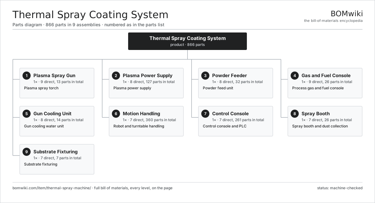
| # | Part | Qty | What it does |
|---|---|---|---|
| 1 | Plasma Spray Gun 9 parts | 1× | Plasma spray torch |
| 2 | Plasma Power Supply 8 parts | 1× | Plasma power supply |
| 3 | Powder Feeder 8 parts | 1× | Powder feed unit |
| 4 | Gas and Fuel Console 9 parts | 1× | Process gas and fuel console |
| 5 | Gun Cooling Unit 8 parts | 1× | Gun cooling water unit |
| 6 | Motion Handling 7 parts | 1× | Robot and turntable handling |
| 7 | Control Console 7 parts | 1× | Control console and PLC |
| 8 | Spray Booth 7 parts | 1× | Spray booth and dust collection |
| 9 | Substrate Fixturing 7 parts | 1× | Substrate fixturing |
3D model
No 3D model yet. Have a CAD file of this? Add a 3D model — STL renders right on this page; STEP, FreeCAD, and OpenSCAD sources are welcome too (openly licensed, like all 3D models on BOMwiki).
Build & assembly graph
expand / collapse · shared sub-assemblies converge · links to related products · est. labourTap an assembly to expand/collapse · tap a part to open it · use “Open page” for any node · drag to pan, scroll to zoom.
Bill of materials for Thermal Spray Coating System
9 top-level lines · 112 rows shown · 866 parts total · indented to 3 levels| # | Item / sub-assembly | Part no. | Qty/assy | Ext. qty | Parts | Type |
|---|---|---|---|---|---|---|
| 1 | Plasma Spray Gun 9 parts | thermal-spray-machine-spray-gun | 1× | 1 | 13 | assembly |
| 1.1 | Thoriated Tungsten Cathode | thermal-spray-machine-cathode | 1× | 1 | · | part |
| 1.2 | Copper Anode Nozzle | thermal-spray-machine-anode-nozzle | 1× | 1 | · | part |
| 1.3 | Swirl Gas Injector | thermal-spray-machine-gas-injector | 1× | 1 | · | part |
| 1.4 | Powder Injection Port | thermal-spray-machine-powder-port | 2× | 2 | · | part |
| 1.5 | Gun Body | thermal-spray-machine-gun-body | 1× | 1 | · | part |
| 1.6 | Inter-Electrode Insulator | thermal-spray-machine-gun-insulator | 1× | 1 | · | part |
| 1.7 | Electrode Coolant Jacket | thermal-spray-machine-electrode-coolant-jacket | 1× | 1 | · | part |
| 1.8 | O-Ring Set | oring-set | 4× | 4 | · | part |
| 1.9 | Fastener Set | fastener-set | 1× | 1 | · | part |
| 2 | Plasma Power Supply 8 parts | thermal-spray-machine-power-source | 1× | 1 | 127 | assembly |
| 2.1 | Thyristor Rectifier Stack | thermal-spray-machine-rectifier-stack | 1× | 1 | · | part |
| 2.2 | Main Power Transformer | thermal-spray-machine-main-transformer | 1× | 1 | · | part |
| 2.3 | Smoothing Choke | thermal-spray-machine-smoothing-choke | 1× | 1 | · | part |
| 2.4 | HF Arc Igniter 3 parts | thermal-spray-machine-hf-igniter | 1× | 1 | 32 | assembly |
| 2.4.1 | Bare PCB | pcb-bare | 1× | 1 | · | part |
| 2.4.2 | HF Spark Gap | thermal-spray-machine-spark-gap | 1× | 1 | · | part |
| 2.4.3 | SMD Passive (R/C/L) | smd-passives | 30× | 30 | · | part |
| 2.5 | Arc Current Regulator 4 parts | thermal-spray-machine-current-regulator | 1× | 1 | 88 | assembly |
| 2.5.1 | Bare PCB | pcb-bare | 1× | 1 | · | part |
| 2.5.2 | Microcontroller | mcu | 1× | 1 | · | part |
| 2.5.3 | SMD Passive (R/C/L) | smd-passives | 80× | 80 | · | part |
| 2.5.4 | Connector | connector | 6× | 6 | · | part |
| 2.6 | Line Contactor | thermal-spray-machine-power-contactor | 2× | 2 | · | part |
| 2.7 | Output Bus Bar | thermal-spray-machine-bus-bar | 1× | 1 | · | part |
| 2.8 | Power Supply | power-supply | 1× | 1 | · | part |
| 3 | Powder Feeder 8 parts | thermal-spray-machine-powder-feeder | 1× | 1 | 32 | assembly |
| 3.1 | Powder Hopper | thermal-spray-machine-powder-hopper | 1× | 1 | · | part |
| 3.2 | Metering Wheel | thermal-spray-machine-feed-wheel | 1× | 1 | · | part |
| 3.3 | Feed Wheel Drive | thermal-spray-machine-feed-motor | 1× | 1 | · | part |
| 3.4 | Carrier Gas Regulator | thermal-spray-machine-carrier-regulator | 1× | 1 | · | part |
| 3.5 | Powder Mass-Flow Sensor | thermal-spray-machine-powder-mass-sensor | 1× | 1 | · | part |
| 3.6 | Hopper Vibrator | thermal-spray-machine-vibrator | 1× | 1 | · | part |
| 3.7 | Servo Motor 4 parts | servo-motor | 1× | 1 | 24 | assembly |
| 3.7.1 | Stator Assembly 3 parts + deeper › | stator-assembly | 1× | 1 | 3 | assembly |
| 3.7.2 | Rotor Assembly 4 parts + deeper › | rotor-assembly | 1× | 1 | 19 | assembly |
| 3.7.3 | Encoder | encoder | 1× | 1 | · | part |
| 3.7.4 | Motor Housing | motor-housing | 1× | 1 | · | part |
| 3.8 | O-Ring Set | oring-set | 2× | 2 | · | part |
| 4 | Gas and Fuel Console 9 parts | thermal-spray-machine-gas-console | 1× | 1 | 26 | assembly |
| 4.1 | Argon Mass-Flow Controller | thermal-spray-machine-argon-mfc | 1× | 1 | · | part |
| 4.2 | Hydrogen Mass-Flow Controller | thermal-spray-machine-hydrogen-mfc | 1× | 1 | · | part |
| 4.3 | Nitrogen Mass-Flow Controller | thermal-spray-machine-nitrogen-mfc | 1× | 1 | · | part |
| 4.4 | Carrier Mass-Flow Controller | thermal-spray-machine-carrier-mfc | 1× | 1 | · | part |
| 4.5 | Gas Manifold | thermal-spray-machine-gas-manifold | 1× | 1 | · | part |
| 4.6 | Solenoid Valve Bank 3 parts | thermal-spray-machine-solenoid-bank | 1× | 1 | 14 | assembly |
| 4.6.1 | Gas Solenoid Valve | thermal-spray-machine-gas-solenoid | 5× | 5 | · | part |
| 4.6.2 | Connector | connector | 8× | 8 | · | part |
| 4.6.3 | Fastener Set | fastener-set | 1× | 1 | · | part |
| 4.7 | Flashback Arrestor | thermal-spray-machine-flashback-arrestor | 2× | 2 | · | part |
| 4.8 | Pressure Sensor | pressure-sensor | 4× | 4 | · | part |
| 4.9 | Fastener Set | fastener-set | 1× | 1 | · | part |
| 5 | Gun Cooling Unit 8 parts | thermal-spray-machine-cooling-unit | 1× | 1 | 14 | assembly |
| 5.1 | Refrigerated Chiller | thermal-spray-machine-chiller | 1× | 1 | · | part |
| 5.2 | Coolant Pump | thermal-spray-machine-coolant-pump | 1× | 1 | · | part |
| 5.3 | Plate Heat Exchanger | thermal-spray-machine-heat-exchanger | 1× | 1 | · | part |
| 5.4 | Deionizing Cartridge | thermal-spray-machine-di-cartridge | 1× | 1 | · | part |
| 5.5 | Coolant Hose | thermal-spray-machine-coolant-hose | 4× | 4 | · | part |
| 5.6 | Flow Switch | thermal-spray-machine-flow-switch | 2× | 2 | · | part |
| 5.7 | Coolant Tank | thermal-spray-machine-coolant-tank | 1× | 1 | · | part |
| 5.8 | O-Ring Set | oring-set | 3× | 3 | · | part |
| 6 | Motion Handling 7 parts | thermal-spray-machine-motion | 1× | 1 | 360 | assembly |
| 6.1 | Spray Robot 4 parts | thermal-spray-machine-robot-arm | 1× | 1 | 306 | assembly |
| 6.1.1 | Servo Motor 4 parts + deeper › | servo-motor | 6× | 6 | 24 | assembly |
| 6.1.2 | Gearbox Housing | gearbox-housing | 6× | 6 | · | part |
| 6.1.3 | Robot Controller 4 parts + deeper › | thermal-spray-machine-robot-controller | 1× | 1 | 154 | assembly |
| 6.1.4 | Wire Bundle | wire-bundle | 2× | 2 | · | part |
| 6.2 | Part Turntable | thermal-spray-machine-turntable | 1× | 1 | · | part |
| 6.3 | Gun Mount Bracket | thermal-spray-machine-gun-mount | 1× | 1 | · | part |
| 6.4 | Traverse Rail | thermal-spray-machine-traverse-rail | 1× | 1 | · | part |
| 6.5 | Linear Guide Rail | linear-guide | 2× | 2 | · | part |
| 6.6 | Ball Screw | ball-screw | 1× | 1 | · | part |
| 6.7 | Servo Motor 4 parts | servo-motor | 2× | 2 | 24 | assembly |
| 6.7.1 | Stator Assembly 3 parts + deeper › | stator-assembly | 1× | 2 | 3 | assembly |
| 6.7.2 | Rotor Assembly 4 parts + deeper › | rotor-assembly | 1× | 2 | 19 | assembly |
| 6.7.3 | Encoder | encoder | 1× | 2 | · | part |
| 6.7.4 | Motor Housing | motor-housing | 1× | 2 | · | part |
| 7 | Control Console 7 parts | thermal-spray-machine-control | 1× | 1 | 261 | assembly |
| 7.1 | Process PLC 5 parts | thermal-spray-machine-plc | 1× | 1 | 192 | assembly |
| 7.1.1 | Bare PCB | pcb-bare | 1× | 1 | · | part |
| 7.1.2 | Microcontroller | mcu | 2× | 2 | · | part |
| 7.1.3 | Power Supply | power-supply | 1× | 1 | · | part |
| 7.1.4 | Relay | relay | 8× | 8 | · | part |
| 7.1.5 | SMD Passive (R/C/L) | smd-passives | 180× | 180 | · | part |
| 7.2 | Operator Console 3 parts | thermal-spray-machine-hmi | 1× | 1 | 3 | assembly |
| 7.2.1 | LCD Panel | lcd-panel | 1× | 1 | · | part |
| 7.2.2 | Bare PCB | pcb-bare | 1× | 1 | · | part |
| 7.2.3 | Microcontroller | mcu | 1× | 1 | · | part |
| 7.3 | Safety Interlock | thermal-spray-machine-interlock | 1× | 1 | · | part |
| 7.4 | I/O Rack 3 parts | thermal-spray-machine-io-rack | 1× | 1 | 37 | assembly |
| 7.4.1 | Bare PCB | pcb-bare | 1× | 1 | · | part |
| 7.4.2 | Relay | relay | 16× | 16 | · | part |
| 7.4.3 | Connector | connector | 20× | 20 | · | part |
| 7.5 | Emergency Stop Station | thermal-spray-machine-estop | 2× | 2 | · | part |
| 7.6 | Wire Bundle | wire-bundle | 2× | 2 | · | part |
| 7.7 | Connector | connector | 24× | 24 | · | part |
| 8 | Spray Booth 7 parts | thermal-spray-machine-booth | 1× | 1 | 26 | assembly |
| 8.1 | Booth Enclosure | thermal-spray-machine-booth-enclosure | 1× | 1 | · | part |
| 8.2 | Exhaust Fan | thermal-spray-machine-exhaust-fan | 1× | 1 | · | part |
| 8.3 | Dust Collector | thermal-spray-machine-dust-collector | 1× | 1 | · | part |
| 8.4 | Filter Cartridge | thermal-spray-machine-cartridge-filter | 8× | 8 | · | part |
| 8.5 | Spark Trap | thermal-spray-machine-spark-trap | 1× | 1 | · | part |
| 8.6 | Acoustic Window | thermal-spray-machine-acoustic-window | 2× | 2 | · | part |
| 8.7 | Sheet Metal Panel | sheet-panel | 12× | 12 | · | part |
| 9 | Substrate Fixturing 7 parts | thermal-spray-machine-fixturing | 1× | 1 | 7 | assembly |
| 9.1 | Part Chuck | thermal-spray-machine-part-chuck | 1× | 1 | · | part |
| 9.2 | Masking Set | thermal-spray-machine-masking-set | 1× | 1 | · | part |
| 9.3 | Preheat Element | thermal-spray-machine-preheat-element | 1× | 1 | · | part |
| 9.4 | Surface Pyrometer | thermal-spray-machine-pyrometer | 1× | 1 | · | part |
| 9.5 | Grit-Blast Head | thermal-spray-machine-grit-blast-head | 1× | 1 | · | part |
| 9.6 | Heating Element | heating-element | 1× | 1 | · | part |
| 9.7 | Fastener Set | fastener-set | 1× | 1 | · | part |
Related products
same domain, ranked by shared parts Rubber Extrusion Line
524 parts · shares 24 with this page
Powder Coating Line
5,418 parts · shares 24 with this page
Rubber Extrusion Line
524 parts · shares 24 with this page
Powder Coating Line
5,418 parts · shares 24 with this page
 Continuous Galvanizing Line
1,296 parts · shares 23 with this page
Continuous Galvanizing Line
1,296 parts · shares 23 with this page
 Industrial Ultrasonic Cleaner
787 parts · shares 24 with this page
Micro Injection Molding Machine
704 parts · shares 24 with this page
Industrial Ultrasonic Cleaner
787 parts · shares 24 with this page
Micro Injection Molding Machine
704 parts · shares 24 with this page
Sourcing: possible vendors
Prices, MOQ, and lead times are algorithmic estimates, not quotes, and not claims about these companies. Company mappings are curated by keyword; est. price band $5k–$2M. How estimates work| Vendor | HQ | Specialty | MOQ | Lead time |
|---|---|---|---|---|
| atlascopco.com ↗ | Stockholm, SE | Compressors & industrial | 10 units | 12–20 wks |
|
🇦🇹Andritz
andritz.com ↗
|
Graz, AT | Process plants & machinery | 10 units | 12–20 wks |
| buhlergroup.com ↗ | Uzwil, CH | Food & materials processing | 10 units | 12–20 wks |
| gea.com ↗ | Düsseldorf, DE | Process technology | 10 units | 12–20 wks |
| mhi.com ↗ | Tokyo, JP | Heavy machinery | 10 units | 12–20 wks |
1,300-word article