Electrolyte Filling Machine
ProductOverview
An electrolyte filling machine is a precision dispensing system designed to safely inject liquid electrolyte into battery cells within an inert (nitrogen or argon) atmosphere. Lithium-ion electrolyte, typically a solution of lithium salts (LiPF₆, LiBF₄) in organic solvents (carbonate esters, ethers), is hygroscopic and reacts violently with water and oxygen. Electrolyte filling must occur in a dry, oxygen-free environment, hence integration with a Glove-Box Airlock (glovebox).
The machine uses vacuum desolvation (partial degassing of the jelly-roll before filling), precision dosing (metering exact volumes to avoid overfill), thermal sealing (hermetically sealing the pouch), and vision inspection (detecting leaks or underfill) in a coordinated sequence.
How It Works
A completed jelly-roll, wrapped in a pre-cut aluminum or polyester-aluminum pouch (open on one edge), is loaded into the Glove-Box Airlock airlock. The airlock is purged with nitrogen gas, venting air and moisture to below 50 ppm O₂ and <50 ppm H₂O.
The pouch is then transferred into the main Vacuum Chamber & Pump via a transfer lock. The chamber is pumped down to <10 mbar absolute pressure using the Rotary Vane Vacuum Pump, a rotary vane pump with oil sealing. This 30–60 second pump-down removes dissolved gases and moisture from the jelly-roll and pouch interior, critical for long cell lifetime (outgassing during use would increase impedance and reduce power output).
Once vacuum is achieved, the Vacuum Throttle Valve is opened slightly, allowing nitrogen to slowly repressurize the chamber. Simultaneously, the Multi-Needle Dosing Head lowers precision needles into the pouch. The Servo-Metered Pump System system activates the Peristaltic Pump Head, drawing pre-heated electrolyte from a reservoir and dispensing it through 2–8 needles at 0.1–10 mL/min per needle.
The Electrolyte Heater maintains electrolyte at 30–50°C to reduce viscosity and ensure smooth flow. A pump encoder counts rotations to track dispensed volume; a Pressure Sensor monitors outlet pressure (confirming needle not clogged). Vision inspection via Vision Inspection Module monitors the rising meniscus inside the translucent pouch, confirming target volume (e.g., 10 mL) is reached.
Once fill is complete, the needles retract. The Heat Seal Head applies heat (50–200°C) and pressure (5–20 N per jaw) to the pouch edge for 1–3 seconds, thermally bonding the aluminum and polymer layers into a hermetic seal.
A final vision inspection checks for leaks (no electrolyte weeping from seal) and proper fill level (no underfill). Pass/fail results are logged. The sealed cell exits the machine and proceeds to formation cycling (Battery Formation System) or storage.
Vacuum Degassing and Pouch Preparation
Jelly-rolls contain 10–20% void fraction, pores within the electrode coating and gaps between winding layers. These voids contain air, moisture, and residual solvents (NMP, water). Operating a cell with air-filled pores causes:
- Gassing: During charging, electrolyte decomposes at the air-electrolyte interface, generating CO₂, CO, and ethylene, increasing pressure and impedance.
- Reduced conductivity: Air is insulating; it increases ion-transport resistance.
Vacuum desolvation pulls out dissolved gases and residual water, reducing outgassing and improving calendar life by 10–50%.
Pre-formed pouches (aluminum-plastic laminate) are pre-cut on three sides, open on one edge. Jelly-rolls are inserted before filling. Pouches are typically 1–2 mm thick, with outer dimensions 50×80–100×150 mm depending on cell size. The pouch acts as mechanical containment and protection against oxidation; the hermetic seal created by the Heat Seal Head is critical, a poor seal allows slow air ingress over months, degrading the cell.
Dosing Precision and Volume Control
Electrolyte fill volume is 5–20 mL depending on cell capacity. Over-fill (>20% excess) causes high pressure during charging, venting through safety vents; under-fill (<15% deficit) reduces contact between electrode and electrolyte, increasing impedance.
The Servo-Metered Pump System system uses two feedback loops:
- Encoder-based volumetric counting: A calibrated pump with encoder tracks revolutions, computing dispensed volume in real-time. At 100 PPR encoder resolution and 0.5 cc/rev pump, each encoder pulse equals 5 microliters.
- Pressure monitoring: If outlet pressure spikes (needle blockage), flow stops automatically.
Vision-based meniscus detection (optional upgrade) detects the fill level optically, allowing dynamic adjustment if the encoder drifts. This brings accuracy to ±2%.
Thermal Sealing and Pouch Closure
The Heat Seal Head jaws are heated to 50–200°C. The temperature is tuned to the pouch laminate: aluminum melts at 660°C, but the polyethylene or polypropylene outer layer softens at 100–120°C. A 100–150°C seal temperature bonds the layers without melting them.
Sealing dwell time is 1–3 seconds per pouch edge. Two passes (edge sealing followed by center sealing) improve hermetic quality. Seal force is 5–20 N (measured by Pressure Sensor load-cell under the jaw); too little force leaves voids, too much crushes the pouch.
Integration with Glove-Box Atmosphere
Industrial gloveboxes maintain <50 ppm O₂ and <50 ppm H₂O via nitrogen-purge loops and molecular sieve driers. The Glove-Box Airlock airlock is a dual-ported transfer lock: the external port connects to the machine's vacuum chamber, the internal port to the glovebox. A Solenoid Vent Valve nitrogen purge valve cycles the airlock between machine vacuum and glovebox atmosphere, maintaining inert conditions.
Vision Inspection and Defect Detection
The Vision Inspection Module camera (100+ fps) monitors:
- Fill level: Measures meniscus height or electrolyte volume via image analysis (pixel-area correlation to mL).
- Leak detection: Scans the seal area post-thermal seal for any electrolyte weeping.
- Pouch integrity: Detects wrinkles, holes, or delamination.
A high-speed camera (100 fps) allows real-time feedback during filling, if fill is slow (needle clogged), an alarm triggers and the operator is prompted to clear the needle.
Throughput and Production Scale
Single-needle machines (laboratory) achieve 20–40 pouches/hour. Multi-needle machines (2–8 needles, parallel fill) reach 120–200 pouches/hour by filling multiple pouches simultaneously. Industrial production lines chain multiple filling machines in series for throughput exceeding 500 cells/hour.
Safety and Environmental Control
Electrolyte is a health hazard (skin irritant, respiratory sensitizer). The Rotary Vane Vacuum Pump exhaust is vented to a fume hood or scrubber. Operator gloves (nitrile, butyl rubber) are mandatory. The glovebox maintains negative pressure (< -10 Pa relative to room), preventing leaks from escaping.
Spill containment trays are placed under the machine. Regular maintenance includes flushing pump heads and needles with acetone or isopropanol to remove electrolyte residue.
Electrolyte Filling Machine parts and their functions
8 top-level parts · 42 parts in total · full bill of materials below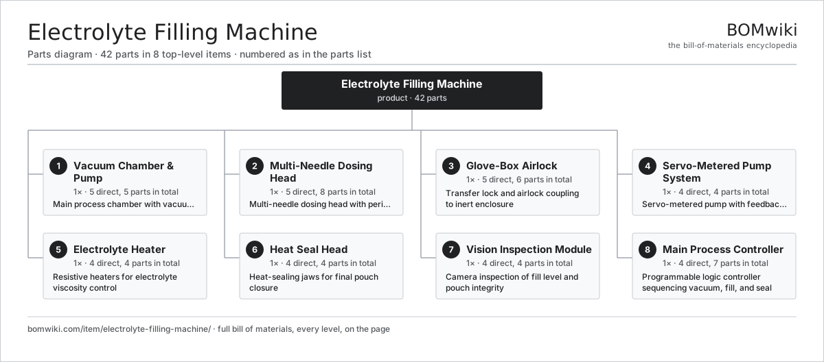
| # | Part | Qty | What it does |
|---|---|---|---|
| 1 | Vacuum Chamber & Pump 5 parts | 1× | Main process chamber with vacuum pump and throttle valve |
| 2 | Multi-Needle Dosing Head 5 parts | 1× | Multi-needle dosing head with peristaltic pump array |
| 3 | Glove-Box Airlock 5 parts | 1× | Transfer lock and airlock coupling to inert enclosure |
| 4 | Servo-Metered Pump System 4 parts | 1× | Servo-metered pump with feedback dispense volume |
| 5 | Electrolyte Heater 4 parts | 1× | Resistive heaters for electrolyte viscosity control |
| 6 | Heat Seal Head 4 parts | 1× | Heat-sealing jaws for final pouch closure |
| 7 | Vision Inspection Module 4 parts | 1× | Camera inspection of fill level and pouch integrity |
| 8 | Main Process Controller 4 parts | 1× | Programmable logic controller sequencing vacuum, fill, and seal |
3D model
No 3D model yet. Have a CAD file of this? Add a 3D model. STL renders right on this page; STEP, FreeCAD, and OpenSCAD sources are welcome too (openly licensed, like all 3D models on BOMwiki).
Build & assembly graph
expand / collapse · shared sub-assemblies converge · links to related products · est. labourTap an assembly to expand/collapse · tap a part to open it · use “Open page” for any node · drag to pan, scroll to zoom.
Bill of materials for Electrolyte Filling Machine
8 top-level lines · 43 rows shown · 42 parts total · indented to 3 levels| # | Item / sub-assembly | Part no. | Qty/assy | Ext. qty | Parts | Type |
|---|---|---|---|---|---|---|
| 1 | Vacuum Chamber & Pump 5 parts | electrolyte-filling-machine-vacuum-chamber | 1× | 1 | 5 | assembly |
| 1.1 | Vacuum Chamber | electrolyte-filling-machine-chamber-vessel | 1× | 1 | · | part |
| 1.2 | Rotary Vane Vacuum Pump | electrolyte-filling-machine-vacuum-pump | 1× | 1 | · | part |
| 1.3 | Vacuum Throttle Valve | electrolyte-filling-machine-throttle-valve | 1× | 1 | · | part |
| 1.4 | Vacuum Gauge | electrolyte-filling-machine-pressure-gauge | 1× | 1 | · | part |
| 1.5 | Pressure Sensor | pressure-sensor | 1× | 1 | · | part |
| 2 | Multi-Needle Dosing Head 5 parts | electrolyte-filling-machine-needle-station | 1× | 1 | 8 | assembly |
| 2.1 | Peristaltic Pump Head | electrolyte-filling-machine-peristaltic-pump | 4× | 4 | · | part |
| 2.2 | Pump Drive Motor | electrolyte-filling-machine-pump-motor | 1× | 1 | · | part |
| 2.3 | Dosing Needles | electrolyte-filling-machine-needle-set | 1× | 1 | · | part |
| 2.4 | Needle Block | electrolyte-filling-machine-needle-holder | 1× | 1 | · | part |
| 2.5 | Connector | connector | 1× | 1 | · | part |
| 3 | Glove-Box Airlock 5 parts | electrolyte-filling-machine-glove-box-interface | 1× | 1 | 6 | assembly |
| 3.1 | Transfer Lock Chamber | electrolyte-filling-machine-transfer-lock | 1× | 1 | · | part |
| 3.2 | Check Valve | electrolyte-filling-machine-check-valve | 2× | 2 | · | part |
| 3.3 | Solenoid Vent Valve | electrolyte-filling-machine-solenoid-vent | 1× | 1 | · | part |
| 3.4 | Pouch Loading Tray | electrolyte-filling-machine-loading-tray | 1× | 1 | · | part |
| 3.5 | Connector | connector | 1× | 1 | · | part |
| 4 | Servo-Metered Pump System 4 parts | electrolyte-filling-machine-dosage-control | 1× | 1 | 4 | assembly |
| 4.1 | Positive Displacement Pump | electrolyte-filling-machine-gear-pump | 1× | 1 | · | part |
| 4.2 | Pump Encoder | electrolyte-filling-machine-pump-encoder | 1× | 1 | · | part |
| 4.3 | Pump Stop-Check Solenoid | electrolyte-filling-machine-pump-solenoid | 1× | 1 | · | part |
| 4.4 | Pressure Sensor | pressure-sensor | 1× | 1 | · | part |
| 5 | Electrolyte Heater 4 parts | electrolyte-filling-machine-heating-module | 1× | 1 | 4 | assembly |
| 5.1 | Immersion Heater | electrolyte-filling-machine-heater-element | 1× | 1 | · | part |
| 5.2 | Temperature Probe | electrolyte-filling-machine-temperature-sensor | 1× | 1 | · | part |
| 5.3 | PID Temperature Controller | electrolyte-filling-machine-temperature-controller | 1× | 1 | · | part |
| 5.4 | Relay | relay | 1× | 1 | · | part |
| 6 | Heat Seal Head 4 parts | electrolyte-filling-machine-sealing-head | 1× | 1 | 4 | assembly |
| 6.1 | Heat Seal Jaws | electrolyte-filling-machine-seal-jaw-pair | 1× | 1 | · | part |
| 6.2 | Seal Jaw Heater | electrolyte-filling-machine-seal-heater | 1× | 1 | · | part |
| 6.3 | Seal Jaw Actuator | electrolyte-filling-machine-seal-actuator | 1× | 1 | · | part |
| 6.4 | Pressure Sensor | pressure-sensor | 1× | 1 | · | part |
| 7 | Vision Inspection Module 4 parts | electrolyte-filling-machine-vision-qa | 1× | 1 | 4 | assembly |
| 7.1 | CMOS Image Sensor | image-sensor | 1× | 1 | · | part |
| 7.2 | Lens Assembly | camera-lens | 1× | 1 | · | part |
| 7.3 | LED Coaxial Illuminator | cell-winding-machine-lighting-unit | 1× | 1 | · | part |
| 7.4 | Bare PCB | pcb-bare | 1× | 1 | · | part |
| 8 | Main Process Controller 4 parts | electrolyte-filling-machine-controller | 1× | 1 | 7 | assembly |
| 8.1 | Microcontroller | mcu | 1× | 1 | · | part |
| 8.2 | HMI Touchscreen | electrolyte-filling-machine-touch-hmi | 1× | 1 | · | part |
| 8.3 | Power Supply | power-supply | 2× | 2 | · | part |
| 8.4 | Relay | relay | 3× | 3 | · | part |
Something wrong in this list? Report a problem with this BOM.
Related products
same domain, ranked by shared parts Pouch Sealing Machine
38 parts · shares 5 with this page
 Wafer Dicing Saw
44 parts · shares 4 with this page
Sourcing: possible vendors
Browse the supplier directory → Prices, MOQ, and lead times are algorithmic estimates, not quotes, and not claims about these companies. Company mappings are curated by keyword; est. price band $5k–$2M. How estimates work| Vendor | HQ | Specialty | MOQ | Lead time |
|---|---|---|---|---|
| atlascopco.com ↗ | Stockholm, SE | Compressors & industrial | 10 units | 12–20 wks |
|
🇦🇹Andritz
andritz.com ↗
|
Graz, AT | Process plants & machinery | 10 units | 12–20 wks |
| buhlergroup.com ↗ | Uzwil, CH | Food & materials processing | 10 units | 12–20 wks |
| gea.com ↗ | Düsseldorf, DE | Process technology | 10 units | 12–20 wks |
| mhi.com ↗ | Tokyo, JP | Heavy machinery | 10 units | 12–20 wks |
1,114-word article