Ribbon Blender
ProductOverview
A ribbon blender is a horizontal batch mixer built around a U-shaped trough and a double-helical ribbon agitator. It is the workhorse of dry powder and granule blending across food production: spice blends, drink mixes, baking premixes, instant soups, dry pet food, and protein powders. The geometry is simple but the action is precise. The agitator carries two concentric helical ribbons wound in opposite directions on a single shaft. The outer ribbon pushes material from the trough ends toward the center, while the inner ribbon moves material from the center back toward the ends. The two opposing flows create a tumbling, radial and axial movement that distributes ingredients evenly without grinding or generating heat.
Ribbon blenders handle batches from a few cubic feet to several thousand. The working capacity is usually 40 to 80 percent of the total trough volume, because the ribbon needs headroom above the material bed to lift and fold powder. A typical mix completes in 5 to 20 minutes and reaches a coefficient of variation below 5 percent, the standard measure of blend uniformity. The Mixing Trough and Ribbon Agitator are the two parts that define the machine; everything else supports, drives, seals, or controls them.
Mixing trough
The Mixing Trough is the vessel that contains the batch. Its cross section is a U so the bottom radius matches the swept path of the outer ribbon, leaving a uniform clearance of 3 to 6 millimeters between the ribbon edge and the wall. This tight clearance prevents stagnant material from collecting at the bottom. The shell and the Trough End Plate pair are typically 316L stainless steel for corrosive or salty food products, with a polished Polished Inner Liner surface finished to 0.4 to 0.8 micron Ra to meet sanitary requirements and shed product cleanly.
Many food applications need temperature control during mixing, for example to warm fat-containing premixes or cool heat-sensitive blends. An optional Thermal Jacket Shell wraps the trough so steam, hot water, or chilled water circulates through the gap. The Jacket Inlet/Outlet Fitting connections distribute the thermal fluid evenly and a pressure rating of 15 to 150 psi covers most steam services.
Agitator and drive
The Ribbon Agitator is a single shaft carrying the Outer Helical Ribbon and the Inner Helical Ribbon, both held off the shaft by radial Ribbon Support Arm arms. The opposing helix angles set the balance between axial conveying and radial folding. Ribbon pitch, width, and the number of starts are tuned to the bulk density and flow character of the product. A light, free-flowing powder needs a different ribbon geometry than a cohesive, fatty premix.
Power comes from the Drive Unit. A TEFC TEFC Motor (5-30 hp) of 5 to 30 hp turns through a Helical Gearbox helical reducer that brings the speed down to the 30 to 60 rpm range. A Flexible Shaft Coupling joins the reducer output to the agitator shaft, and a Variable Frequency Drive lets the operator trim speed for gentle ingredients or speed up for fast discharge. Running too fast wastes energy and can cause segregation; running too slow lengthens the cycle.
Bearings, seals, and discharge
Each end of the shaft passes through the end plate and rides in a Shaft Bearing Station. An outboard pillow block carries the radial load while a Stuffing Box with Gland Packing Rope seals the shaft penetration against product leakage and dust escape. Keeping the bearings outside the product zone prevents grease contamination and makes inspection easy.
The batch leaves through the Discharge Valve at the lowest point of the trough. A flush slide gate or butterfly valve sits exactly level with the inner wall so no product ledge remains after discharge. A Pneumatic Cylinder drives the slide open and shut, and the agitator can keep turning during discharge to sweep the trough clean.
Cover and controls
The Top Cover closes the top of the trough to contain dust and keep the batch clean. It carries Material Feed Port openings for charging ingredients, a Vent Dust Filter for connection to dust collection, and a Safety Grate over each port to keep hands clear of the moving ribbon. A Cover Interlock Switch interlock stops the drive whenever the cover is opened.
The Control Panel holds the PLC Module and an HMI Touchscreen touchscreen for recipe selection, batch timing, and fault display. A motor DC Contactor pair and an E-Stop Button complete the safety chain.
Materials and sanitation
Food-grade ribbon blenders are built almost entirely from 304 or 316L stainless steel, with the higher grade used wherever salt, acid, or chloride exposure is likely. Welds in the product zone are ground flush and polished to eliminate crevices where product or bacteria could lodge. Designs intended for frequent allergen changeover use clamped, tool-free access panels so the whole interior can be wiped or washed between recipes. Where wet cleaning is needed, the trough drains fully through the flush discharge valve and the jacket can run hot water for sanitizing.
Variants and use
Plough mixers, paddle mixers, and ribbon blenders share the horizontal trough format but differ in agitator action. The ribbon design is preferred when gentle, low-shear blending of dry solids is the goal and when minor liquid additions are sprayed in. For very cohesive or paste-like products, a paddle or plough is often chosen instead. Ribbon blenders scale predictably, so a recipe proven on a small machine transfers cleanly to a production unit of the same geometry, which is why they remain standard equipment in food powder plants.
Ribbon Blender parts and their functions
8 top-level parts · 321 parts in total · full bill of materials below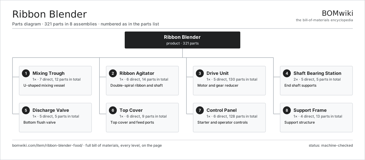
| # | Part | Qty | What it does |
|---|---|---|---|
| 1 | Mixing Trough 7 parts | 1× | U-shaped mixing vessel |
| 2 | Ribbon Agitator 6 parts | 1× | Double-spiral ribbon and shaft |
| 3 | Drive Unit 5 parts | 1× | Motor and gear reducer |
| 4 | Shaft Bearing Station 5 parts | 2× | End shaft supports |
| 5 | Discharge Valve 5 parts | 1× | Bottom flush valve |
| 6 | Top Cover 6 parts | 1× | Top cover and feed ports |
| 7 | Control Panel 6 parts | 1× | Starter and operator controls |
| 8 | Support Frame 4 parts | 1× | Support structure |
3D model
No 3D model yet. Have a CAD file of this? Add a 3D model — STL renders right on this page; STEP, FreeCAD, and OpenSCAD sources are welcome too (openly licensed, like all 3D models on BOMwiki).
Build & assembly graph
expand / collapse · shared sub-assemblies converge · links to related products · est. labourTap an assembly to expand/collapse · tap a part to open it · use “Open page” for any node · drag to pan, scroll to zoom.
Bill of materials for Ribbon Blender
8 top-level lines · 72 rows shown · 321 parts total · indented to 3 levels| # | Item / sub-assembly | Part no. | Qty/assy | Ext. qty | Parts | Type |
|---|---|---|---|---|---|---|
| 1 | Mixing Trough 7 parts | ribbon-blender-food-trough | 1× | 1 | 12 | assembly |
| 1.1 | Trough Shell (304/316 SS) | ribbon-blender-food-trough-shell | 1× | 1 | · | part |
| 1.2 | Trough End Plate | ribbon-blender-food-end-plate | 2× | 2 | · | part |
| 1.3 | Polished Inner Liner | ribbon-blender-food-trough-liner | 1× | 1 | · | part |
| 1.4 | Thermal Jacket Shell | ribbon-blender-food-jacket | 1× | 1 | · | part |
| 1.5 | Jacket Inlet/Outlet Fitting | ribbon-blender-food-jacket-fitting | 4× | 4 | · | part |
| 1.6 | O-Ring Set | oring-set | 2× | 2 | · | part |
| 1.7 | Fastener Set | fastener-set | 1× | 1 | · | part |
| 2 | Ribbon Agitator 6 parts | ribbon-blender-food-agitator | 1× | 1 | 14 | assembly |
| 2.1 | Agitator Shaft | ribbon-blender-food-shaft | 1× | 1 | · | part |
| 2.2 | Outer Helical Ribbon | ribbon-blender-food-outer-ribbon | 1× | 1 | · | part |
| 2.3 | Inner Helical Ribbon | ribbon-blender-food-inner-ribbon | 1× | 1 | · | part |
| 2.4 | Ribbon Support Arm | ribbon-blender-food-ribbon-support | 8× | 8 | · | part |
| 2.5 | Shaft Drive Key | ribbon-blender-food-shaft-key | 2× | 2 | · | part |
| 2.6 | Fastener Set | fastener-set | 1× | 1 | · | part |
| 3 | Drive Unit 5 parts | ribbon-blender-food-drive | 1× | 1 | 130 | assembly |
| 3.1 | TEFC Motor (5-30 hp) 5 parts | ribbon-blender-food-motor | 1× | 1 | 26 | assembly |
| 3.1.1 | Stator Assembly 3 parts + deeper › | stator-assembly | 1× | 1 | 3 | assembly |
| 3.1.2 | Rotor Assembly 4 parts + deeper › | rotor-assembly | 1× | 1 | 19 | assembly |
| 3.1.3 | Motor Housing | motor-housing | 1× | 1 | · | part |
| 3.1.4 | Ball Bearing | ball-bearing | 2× | 2 | · | part |
| 3.1.5 | Motor Cooling Fan | ribbon-blender-food-cooling-fan | 1× | 1 | · | part |
| 3.2 | Helical Gearbox 4 parts | gearbox | 1× | 1 | 9 | assembly |
| 3.2.1 | Helical Gear Pair | gear-pair | 2× | 2 | · | part |
| 3.2.2 | Gearbox Housing | gearbox-housing | 1× | 1 | · | part |
| 3.2.3 | Ball Bearing | ball-bearing | 4× | 4 | · | part |
| 3.2.4 | Oil Seal | oil-seal | 2× | 2 | · | part |
| 3.3 | Flexible Shaft Coupling | ribbon-blender-food-coupling | 1× | 1 | · | part |
| 3.4 | Coupling Guard | ribbon-blender-food-guard | 1× | 1 | · | part |
| 3.5 | Variable Frequency Drive 4 parts | ribbon-blender-food-vfd | 1× | 1 | 93 | assembly |
| 3.5.1 | Bare PCB | pcb-bare | 1× | 1 | · | part |
| 3.5.2 | IGBT Power Module | igbt-module | 1× | 1 | · | part |
| 3.5.3 | Power Supply | power-supply | 1× | 1 | · | part |
| 3.5.4 | SMD Passive (R/C/L) | smd-passives | 90× | 90 | · | part |
| 4 | Shaft Bearing Station 5 parts | ribbon-blender-food-bearing-station | 2× | 2 | 5 | assembly |
| 4.1 | Pillow Block Housing | ribbon-blender-food-pillow-block | 1× | 2 | · | part |
| 4.2 | Ball Bearing | ball-bearing | 1× | 2 | · | part |
| 4.3 | Stuffing Box | ribbon-blender-food-stuffing-box | 1× | 2 | · | part |
| 4.4 | Gland Packing Rope | ribbon-blender-food-packing | 1× | 2 | · | part |
| 4.5 | Oil Seal | oil-seal | 1× | 2 | · | part |
| 5 | Discharge Valve 5 parts | ribbon-blender-food-discharge | 1× | 1 | 5 | assembly |
| 5.1 | Slide Valve Body | ribbon-blender-food-valve-body | 1× | 1 | · | part |
| 5.2 | Valve Slide Blade | ribbon-blender-food-valve-blade | 1× | 1 | · | part |
| 5.3 | Valve Actuator Bracket | ribbon-blender-food-valve-actuator | 1× | 1 | · | part |
| 5.4 | Pneumatic Cylinder | pneumatic-cylinder | 1× | 1 | · | part |
| 5.5 | O-Ring Set | oring-set | 1× | 1 | · | part |
| 6 | Top Cover 6 parts | ribbon-blender-food-cover | 1× | 1 | 9 | assembly |
| 6.1 | Cover Panel | ribbon-blender-food-cover-panel | 1× | 1 | · | part |
| 6.2 | Material Feed Port | ribbon-blender-food-feed-port | 2× | 2 | · | part |
| 6.3 | Vent Dust Filter | ribbon-blender-food-vent-filter | 1× | 1 | · | part |
| 6.4 | Safety Grate | ribbon-blender-food-safety-grate | 2× | 2 | · | part |
| 6.5 | Cover Hinge | ribbon-blender-food-cover-hinge | 2× | 2 | · | part |
| 6.6 | Cover Interlock Switch | ribbon-blender-food-cover-switch | 1× | 1 | · | part |
| 7 | Control Panel 6 parts | ribbon-blender-food-control-panel | 1× | 1 | 128 | assembly |
| 7.1 | NEMA 4X Enclosure | ribbon-blender-food-enclosure | 1× | 1 | · | part |
| 7.2 | PLC Module 4 parts | ribbon-blender-food-plc | 1× | 1 | 120 | assembly |
| 7.2.1 | Bare PCB | pcb-bare | 1× | 1 | · | part |
| 7.2.2 | Microcontroller | mcu | 1× | 1 | · | part |
| 7.2.3 | Relay | relay | 8× | 8 | · | part |
| 7.2.4 | SMD Passive (R/C/L) | smd-passives | 110× | 110 | · | part |
| 7.3 | HMI Touchscreen 3 parts | ribbon-blender-food-hmi | 1× | 1 | 3 | assembly |
| 7.3.1 | LCD Panel | lcd-panel | 1× | 1 | · | part |
| 7.3.2 | Bare PCB | pcb-bare | 1× | 1 | · | part |
| 7.3.3 | Microcontroller | mcu | 1× | 1 | · | part |
| 7.4 | DC Contactor | contactor | 2× | 2 | · | part |
| 7.5 | E-Stop Button | ribbon-blender-food-estop | 1× | 1 | · | part |
| 7.6 | Wire Bundle | wire-bundle | 1× | 1 | · | part |
| 8 | Support Frame 4 parts | ribbon-blender-food-frame | 1× | 1 | 13 | assembly |
| 8.1 | Support Leg | ribbon-blender-food-leg | 4× | 4 | · | part |
| 8.2 | Cross Brace | ribbon-blender-food-cross-brace | 4× | 4 | · | part |
| 8.3 | Leveling Foot | ribbon-blender-food-foot | 4× | 4 | · | part |
| 8.4 | Fastener Set | fastener-set | 1× | 1 | · | part |
Related products
same domain, ranked by shared parts Continuous Galvanizing Line
1,296 parts · shares 21 with this page
Continuous Galvanizing Line
1,296 parts · shares 21 with this page
 Decanter Centrifuge
172 parts · shares 19 with this page
Decanter Centrifuge
172 parts · shares 19 with this page
 Pellet Mill
105 parts · shares 19 with this page
Blown Film Extrusion Line
436 parts · shares 19 with this page
Pellet Mill
105 parts · shares 19 with this page
Blown Film Extrusion Line
436 parts · shares 19 with this page
Sourcing: possible vendors
Prices, MOQ, and lead times are algorithmic estimates, not quotes, and not claims about these companies. Company mappings are curated by keyword; est. price band $5k–$2M. How estimates work| Vendor | HQ | Specialty | MOQ | Lead time |
|---|---|---|---|---|
| atlascopco.com ↗ | Stockholm, SE | Compressors & industrial | 10 units | 12–20 wks |
|
🇦🇹Andritz
andritz.com ↗
|
Graz, AT | Process plants & machinery | 10 units | 12–20 wks |
| buhlergroup.com ↗ | Uzwil, CH | Food & materials processing | 10 units | 12–20 wks |
| gea.com ↗ | Düsseldorf, DE | Process technology | 10 units | 12–20 wks |
| mhi.com ↗ | Tokyo, JP | Heavy machinery | 10 units | 12–20 wks |
981-word article