Vibration Welding Machine
ProductOverview
A vibration welding machine joins large or non-round plastic parts that spin welding cannot handle, such as intake manifolds, instrument-panel carriers, door modules, and tail-light housings. Instead of rotating one part, the Vibration Head shakes the upper part back and forth a millimetre or two along the plane of the joint while the Lift Table presses the lower part up against it. The rubbing melts a film of plastic along the whole weld line at once. When melt-down is reached the vibration stops and the parts are held until the joint solidifies. The Control Cabinet runs the recipe and the Frame & Enclosure absorbs the considerable reaction forces.
Because the motion is linear rather than rotary, the weld line can follow almost any closed path in a plane, which is what makes the process suited to the complex perimeters of automotive parts.
How it works
The head drives the upper part in a straight-line oscillation, typically near 240 Hz with an amplitude under two millimetres. The Lift Drive raises the Lift Table so the Lower Fixture presses the lower part against the vibrating upper part under a set force. Friction between the two faces generates heat all along the joint. In the first phase solid surfaces rub and warm; once a melt film forms the parts begin to settle together, and that settling, the melt-down, is what the Displacement Sensor tracks to decide when the weld is done.
The weld ends when a target is met: elapsed time, total energy delivered, or, most commonly for quality parts, a fixed melt-down distance that guarantees a known amount of fresh polymer has been squeezed into the joint. The Drive Amplifier then cuts power, the suspension brings the head to rest within a few cycles, and the lift drive holds force during a hold phase while the melt freezes under pressure. That held pressure is what makes the weld strong and leak-tight.
The resonant drive
The defining feature of the machine is its electromagnetic resonant head. The Vibrating Element is a mass suspended on a stack of Leaf Spring flexures, tuned so that the spring-mass system resonates at the drive frequency. A pair of opposed Drive Electromagnet coils pulse to keep it swinging. At resonance only a small input force is needed to sustain a large amplitude, so the machine is efficient and the amplitude is stable. The Amplitude Sensor feeds peak travel back to the Drive Amplifier, which adjusts drive to hold amplitude constant even as the warming joint changes the load. The whole Head Housing is a heavy casting because the reaction to shaking the part has to go somewhere.
Tooling and clamping
The upper part is gripped by the Upper Tool, whose Upper Tool Plate bolts rigidly to the vibrating element. Any softness here would waste amplitude, so the tooling is solid and the part is held by Part Locator features and often a Vacuum Port so it cannot creep relative to the tool. The lower part sits in the Lower Fixture on the Table Plate, supported close to the weld line so the joint does not flex. The lift table rides Linear Guide Rail rails and is raised by the Lift Cylinder or, on electric machines, a Ball Screw turned by a Servo Motor. A Load Cell closes the force loop through the Lift Valve so melt and forge forces can differ.
Controls and monitoring
The Control Cabinet holds the amplifier and a PLC that sequences lift, vibrate, stop, and hold. Through the LCD Panel the operator picks a recipe and sets amplitude, force, and end criteria. The PLC records force, amplitude, and melt-down for each cycle and compares them with limits, so a weld that did not collapse enough or that drew abnormal power is flagged. A Power Supply feeds the logic and Relay outputs drive the valves and safety chain.
Frame, isolation, and use
Shaking a heavy tool generates a large reaction, so the Main Frame is a massive weldment and the machine stands on Isolation Mount feet that keep the vibration out of the building floor. Acoustic Sheet Metal Panel guarding lowers the noise, and a Light Curtain protects the load opening. Vibration welding dominates large automotive plastic assembly because it welds long perimeters in seconds, tolerates glass-filled and reinforced grades that other methods struggle with, and leaves a strong continuous joint without adhesives or fasteners. It complements rather than replaces spin welding and hot-plate welding: spin welding suits round parts, hot-plate suits parts that must not be marked by motion, and vibration welding handles the large irregular perimeters that neither can reach economically.
Vibration Welding Machine parts and their functions
6 top-level parts · 100 parts in total · full bill of materials below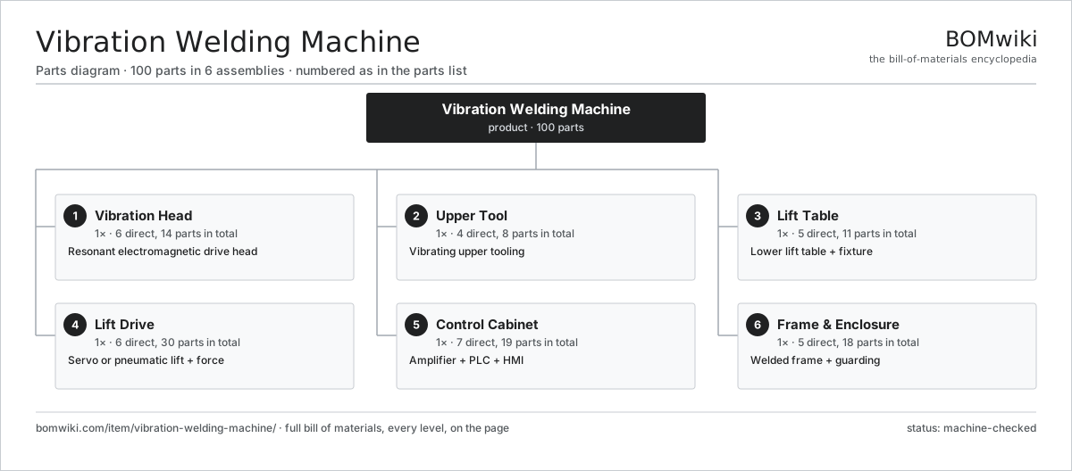
| # | Part | Qty | What it does |
|---|---|---|---|
| 1 | Vibration Head 6 parts | 1× | Resonant electromagnetic drive head |
| 2 | Upper Tool 4 parts | 1× | Vibrating upper tooling |
| 3 | Lift Table 5 parts | 1× | Lower lift table + fixture |
| 4 | Lift Drive 6 parts | 1× | Servo or pneumatic lift + force |
| 5 | Control Cabinet 7 parts | 1× | Amplifier + PLC + HMI |
| 6 | Frame & Enclosure 5 parts | 1× | Welded frame + guarding |
3D model
No 3D model yet. Have a CAD file of this? Add a 3D model — STL renders right on this page; STEP, FreeCAD, and OpenSCAD sources are welcome too (openly licensed, like all 3D models on BOMwiki).
Build & assembly graph
expand / collapse · shared sub-assemblies converge · links to related products · est. labourTap an assembly to expand/collapse · tap a part to open it · use “Open page” for any node · drag to pan, scroll to zoom.
Bill of materials for Vibration Welding Machine
6 top-level lines · 43 rows shown · 100 parts total · indented to 3 levels| # | Item / sub-assembly | Part no. | Qty/assy | Ext. qty | Parts | Type |
|---|---|---|---|---|---|---|
| 1 | Vibration Head 6 parts | vwm-vibration-head | 1× | 1 | 14 | assembly |
| 1.1 | Drive Electromagnet | vwm-electromagnet | 2× | 2 | · | part |
| 1.2 | Vibrating Element | vwm-vibrating-element | 1× | 1 | · | part |
| 1.3 | Leaf Spring | vwm-leaf-spring | 8× | 8 | · | part |
| 1.4 | Amplitude Sensor | vwm-amplitude-sensor | 1× | 1 | · | part |
| 1.5 | Head Housing | vwm-head-housing | 1× | 1 | · | part |
| 1.6 | Fastener Set | fastener-set | 1× | 1 | · | part |
| 2 | Upper Tool 4 parts | vwm-upper-tool | 1× | 1 | 8 | assembly |
| 2.1 | Upper Tool Plate | vwm-upper-tool-plate | 1× | 1 | · | part |
| 2.2 | Part Locator | vwm-part-locator | 4× | 4 | · | part |
| 2.3 | Vacuum Port | vwm-vacuum-port | 2× | 2 | · | part |
| 2.4 | Fastener Set | fastener-set | 1× | 1 | · | part |
| 3 | Lift Table 5 parts | vwm-lifttable | 1× | 1 | 11 | assembly |
| 3.1 | Table Plate | vwm-table-plate | 1× | 1 | · | part |
| 3.2 | Lower Fixture | vwm-lower-fixture | 1× | 1 | · | part |
| 3.3 | Linear Guide Rail | linear-guide | 4× | 4 | · | part |
| 3.4 | Displacement Sensor | vwm-displacement-sensor | 1× | 1 | · | part |
| 3.5 | Table Clamp | vwm-table-clamp | 4× | 4 | · | part |
| 4 | Lift Drive 6 parts | vwm-lift-drive | 1× | 1 | 30 | assembly |
| 4.1 | Lift Cylinder | vwm-lift-cylinder | 2× | 2 | · | part |
| 4.2 | Servo Motor 4 parts | servo-motor | 1× | 1 | 24 | assembly |
| 4.2.1 | Stator Assembly 3 parts + deeper › | stator-assembly | 1× | 1 | 3 | assembly |
| 4.2.2 | Rotor Assembly 4 parts + deeper › | rotor-assembly | 1× | 1 | 19 | assembly |
| 4.2.3 | Encoder | encoder | 1× | 1 | · | part |
| 4.2.4 | Motor Housing | motor-housing | 1× | 1 | · | part |
| 4.3 | Ball Screw | ball-screw | 1× | 1 | · | part |
| 4.4 | Load Cell | vwm-load-cell | 1× | 1 | · | part |
| 4.5 | Lift Valve | vwm-lift-valve | 1× | 1 | · | part |
| 4.6 | Pressure Sensor | pressure-sensor | 1× | 1 | · | part |
| 5 | Control Cabinet 7 parts | vwm-control-cabinet | 1× | 1 | 19 | assembly |
| 5.1 | Drive Amplifier | vwm-drive-amplifier | 1× | 1 | · | part |
| 5.2 | PLC | vwm-plc | 1× | 1 | · | part |
| 5.3 | LCD Panel | lcd-panel | 1× | 1 | · | part |
| 5.4 | Power Supply | power-supply | 1× | 1 | · | part |
| 5.5 | Relay | relay | 6× | 6 | · | part |
| 5.6 | Wire Bundle | wire-bundle | 1× | 1 | · | part |
| 5.7 | Connector | connector | 8× | 8 | · | part |
| 6 | Frame & Enclosure 5 parts | vwm-frame-enclosure | 1× | 1 | 18 | assembly |
| 6.1 | Main Frame | vwm-main-frame | 1× | 1 | · | part |
| 6.2 | Sheet Metal Panel | sheet-panel | 8× | 8 | · | part |
| 6.3 | Isolation Mount | vwm-isolation-mount | 4× | 4 | · | part |
| 6.4 | Light Curtain | vwm-light-curtain | 1× | 1 | · | part |
| 6.5 | Leveling Foot | vwm-leveling-foot | 4× | 4 | · | part |
Related products
same domain, ranked by shared parts Industrial Ultrasonic Cleaner
787 parts · shares 20 with this page
Micro Injection Molding Machine
704 parts · shares 20 with this page
Powder Coating Line
5,418 parts · shares 20 with this page
Industrial Ultrasonic Cleaner
787 parts · shares 20 with this page
Micro Injection Molding Machine
704 parts · shares 20 with this page
Powder Coating Line
5,418 parts · shares 20 with this page
 Thermal Spray Coating System
866 parts · shares 20 with this page
Thermal Spray Coating System
866 parts · shares 20 with this page
 All-Electric Injection Molding Machine
851 parts · shares 19 with this page
All-Electric Injection Molding Machine
851 parts · shares 19 with this page
Sourcing: possible vendors
Prices, MOQ, and lead times are algorithmic estimates, not quotes, and not claims about these companies. Company mappings are curated by keyword; est. price band $5k–$2M. How estimates work| Vendor | HQ | Specialty | MOQ | Lead time |
|---|---|---|---|---|
| atlascopco.com ↗ | Stockholm, SE | Compressors & industrial | 10 units | 12–20 wks |
|
🇦🇹Andritz
andritz.com ↗
|
Graz, AT | Process plants & machinery | 10 units | 12–20 wks |
| buhlergroup.com ↗ | Uzwil, CH | Food & materials processing | 10 units | 12–20 wks |
| gea.com ↗ | Düsseldorf, DE | Process technology | 10 units | 12–20 wks |
| mhi.com ↗ | Tokyo, JP | Heavy machinery | 10 units | 12–20 wks |
805-word article