Vertical Injection Molding Machine
ProductOverview
A vertical injection molding machine stacks the clamp so the mold opens and closes up and down rather than sideways. This is the layout of choice for insert molding and overmolding, where a metal pin, terminal, connector lead, or fastener is placed into the open mold before plastic is injected around it. Because the lower mold half faces up, gravity holds the insert in its pocket while the Vertical Clamp Unit closes onto it. Most of these machines pair the clamp with a Rotary Shuttle Table so the operator loads inserts at one station while the machine molds at the other, which keeps the slow manual loading off the molding cycle.
Injection unit
The Vertical Injection Unit sits above the clamp and injects melt downward. Pellets enter the Feed Hopper and fall into the Water-Cooled Feed Throat of the Plasticizing Barrel, where the turning Reciprocating Screw melts and meters them. The Non-Return Check Ring non-return valve seals during injection, and the Injection Cylinder drives the screw forward to push melt through the Injection Nozzle into the mold sprue. Shot sizes are usually small because insert parts are small, so screws of 22 to 45 mm are typical. The Screw Rotation Drive hydraulic motor turns the screw during the recharge phase.
Vertical clamp
The Vertical Clamp Unit is an up-acting design. The mold's lower half sits on the Lower Platen and the upper half mounts to the Upper Platen. A large-bore Clamp Cylinder develops the full tonnage directly rather than through a toggle, which keeps the open mold face flat and accessible. Four Tie Bar columns guide the motion and carry the clamp load. After the part cures around its insert, the Ejector System drives Ejector Pin sets through the Ejector Plate to release the finished overmolded part.
Rotary shuttle
The productivity of insert molding comes from the Rotary Shuttle Table. Its Turntable Plate carries two lower mold halves at opposite Mold Station positions and rides on a Slewing Bearing. The Index Drive, a servo turning a Cam Indexer, swings the table 180 degrees each cycle so that while one station is under the clamp being molded, the other is at the front where the operator unloads the last part and loads fresh inserts. The slow human step happens in parallel with the fast molding step, so cycle time is set by whichever is longer.
Hydraulic and heating systems
The Hydraulic System supplies clamp, injection, ejection, and the table index from a Hydraulic Pump driven by the Pump Motor. The Valve Block meters injection and clamp speed through a Proportional Valve and sequences functions through Directional Valve elements, with an Oil Cooler holding tank temperature and a Pressure Sensor set feeding the controller. The Barrel Heating System holds the melt profile with a Barrel Band Heater per zone, each built on a Heating Element, read back by a Zone Thermocouple.
Control and safety
The Control System coordinates the half-cycle: it must confirm the operator's hands are clear and the insert is present before it indexes the table and closes the clamp. The Machine Controller runs the sequence and the operator sets parameters on the HMI Touchscreen. Because a person reaches into the loading station every cycle, the Safety System is built around a Light Curtain that stops the index if the beam is broken and a Two-Hand Control that requires both hands on buttons to start, backed by the Emergency Stop.
Materials, variants, and use
Insert molding bonds plastic to metal in one shot, which is how electrical connectors get their terminals encapsulated, how threaded brass inserts are set into housings, and how tool handles are overmolded onto steel shanks. Overmolding adds a soft thermoplastic elastomer grip onto a rigid substrate, common on toothbrushes, power-tool handles, and medical devices. The open Machine Frame C-frame gives clear access on three sides for loading and for robot arms on automated cells. Tonnage is modest, since insert parts are small, but the rotary-table arrangement is what makes the process economical at volume.
Not every vertical machine uses a rotary table. A shuttle-table variant slides two lower halves in and out on a straight track instead of rotating, which suits long or asymmetric inserts that a turntable cannot balance. A simple C-frame machine with a single station is used for low volumes and large single inserts where the operator loads each cycle. The vertical layout has a cost beyond loading convenience: the injection unit sits overhead, so the Machine Frame must carry that weight and the maintenance access to the Plasticizing Barrel is up high. Insert pre-heating is common, since a cold metal insert chills the melt around it and can cause poor bonding or voids, so the loading station sometimes includes a small heater that warms the inserts before molding.
Vertical Injection Molding Machine parts and their functions
8 top-level parts · 264 parts in total · full bill of materials below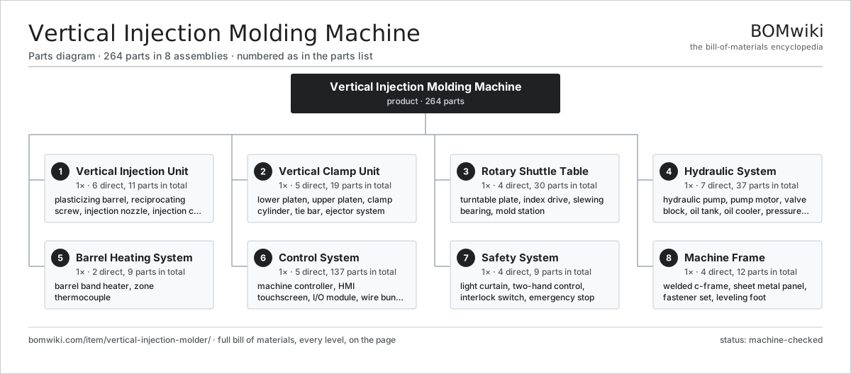
| # | Part | Qty | What it does |
|---|---|---|---|
| 1 | Vertical Injection Unit 6 parts | 1× | Top-mounted reciprocating screw that injects melt downward into the mold. |
| 2 | Vertical Clamp Unit 5 parts | 1× | Up-acting clamp that closes the mold vertically so inserts stay seated by gravity. |
| 3 | Rotary Shuttle Table 4 parts | 1× | Indexing turntable with two lower mold halves so an operator loads inserts off-cycle. |
| 4 | Hydraulic System 7 parts | 1× | Pump and valves powering clamp, injection, ejection, and table index. |
| 5 | Barrel Heating System 2 parts | 1× | Band heaters and thermocouples holding the melt profile. |
| 6 | Control System 5 parts | 1× | Controller sequencing the half-cycle index and injection. |
| 7 | Safety System 4 parts | 1× | Light curtains and two-hand controls protecting the loading station. |
| 8 | Machine Frame 4 parts | 1× | C-frame base carrying the clamp and the overhead injection unit. |
3D model
No 3D model yet. Have a CAD file of this? Add a 3D model — STL renders right on this page; STEP, FreeCAD, and OpenSCAD sources are welcome too (openly licensed, like all 3D models on BOMwiki).
Build & assembly graph
expand / collapse · shared sub-assemblies converge · links to related products · est. labourTap an assembly to expand/collapse · tap a part to open it · use “Open page” for any node · drag to pan, scroll to zoom.
Bill of materials for Vertical Injection Molding Machine
8 top-level lines · 80 rows shown · 264 parts total · indented to 3 levels| # | Item / sub-assembly | Part no. | Qty/assy | Ext. qty | Parts | Type |
|---|---|---|---|---|---|---|
| 1 | Vertical Injection Unit 6 parts | vertical-injection-molder-injection-unit | 1× | 1 | 11 | assembly |
| 1.1 | Plasticizing Barrel 2 parts | vertical-injection-molder-barrel | 1× | 1 | 2 | assembly |
| 1.1.1 | Barrel Tube | vertical-injection-molder-barrel-tube | 1× | 1 | · | part |
| 1.1.2 | Water-Cooled Feed Throat | vertical-injection-molder-feed-throat | 1× | 1 | · | part |
| 1.2 | Reciprocating Screw 2 parts | vertical-injection-molder-screw | 1× | 1 | 2 | assembly |
| 1.2.1 | Screw Body | vertical-injection-molder-screw-body | 1× | 1 | · | part |
| 1.2.2 | Non-Return Check Ring | vertical-injection-molder-check-ring | 1× | 1 | · | part |
| 1.3 | Injection Nozzle 1 parts | vertical-injection-molder-nozzle | 1× | 1 | · | part |
| 1.3.1 | Heating Element | heating-element | 1× | 1 | · | part |
| 1.4 | Injection Cylinder | vertical-injection-molder-injection-cylinder | 1× | 1 | · | part |
| 1.5 | Screw Rotation Drive 3 parts | vertical-injection-molder-screw-drive | 1× | 1 | 4 | assembly |
| 1.5.1 | Hydraulic Motor | vertical-injection-molder-hydraulic-motor | 1× | 1 | · | part |
| 1.5.2 | Helical Gear Pair | gear-pair | 1× | 1 | · | part |
| 1.5.3 | Ball Bearing | ball-bearing | 2× | 2 | · | part |
| 1.6 | Feed Hopper | vertical-injection-molder-hopper | 1× | 1 | · | part |
| 2 | Vertical Clamp Unit 5 parts | vertical-injection-molder-vertical-clamp | 1× | 1 | 19 | assembly |
| 2.1 | Lower Platen | vertical-injection-molder-lower-platen | 1× | 1 | · | part |
| 2.2 | Upper Platen | vertical-injection-molder-upper-platen | 1× | 1 | · | part |
| 2.3 | Clamp Cylinder 4 parts | vertical-injection-molder-clamp-cylinder | 1× | 1 | 5 | assembly |
| 2.3.1 | Cylinder Bore | vertical-injection-molder-cylinder-bore | 1× | 1 | · | part |
| 2.3.2 | Piston Rod | vertical-injection-molder-piston-rod | 1× | 1 | · | part |
| 2.3.3 | O-Ring Set | oring-set | 1× | 1 | · | part |
| 2.3.4 | Oil Seal | oil-seal | 2× | 2 | · | part |
| 2.4 | Tie Bar | vertical-injection-molder-tie-bar | 4× | 4 | · | part |
| 2.5 | Ejector System 3 parts | vertical-injection-molder-ejector | 1× | 1 | 8 | assembly |
| 2.5.1 | Ejector Cylinder | vertical-injection-molder-ejector-cylinder | 1× | 1 | · | part |
| 2.5.2 | Ejector Plate | vertical-injection-molder-ejector-plate | 1× | 1 | · | part |
| 2.5.3 | Ejector Pin | vertical-injection-molder-ejector-pin | 6× | 6 | · | part |
| 3 | Rotary Shuttle Table 4 parts | vertical-injection-molder-rotary-table | 1× | 1 | 30 | assembly |
| 3.1 | Turntable Plate | vertical-injection-molder-table-plate | 1× | 1 | · | part |
| 3.2 | Index Drive 3 parts | vertical-injection-molder-index-drive | 1× | 1 | 26 | assembly |
| 3.2.1 | Servo Motor 4 parts + deeper › | servo-motor | 1× | 1 | 24 | assembly |
| 3.2.2 | Helical Gear Pair | gear-pair | 1× | 1 | · | part |
| 3.2.3 | Cam Indexer | vertical-injection-molder-cam-indexer | 1× | 1 | · | part |
| 3.3 | Slewing Bearing 1 parts | vertical-injection-molder-table-bearing | 1× | 1 | · | part |
| 3.3.1 | Ball Bearing | ball-bearing | 1× | 1 | · | part |
| 3.4 | Mold Station | vertical-injection-molder-clamp-station | 2× | 2 | · | part |
| 4 | Hydraulic System 7 parts | vertical-injection-molder-hydraulic-system | 1× | 1 | 37 | assembly |
| 4.1 | Hydraulic Pump | vertical-injection-molder-pump | 1× | 1 | · | part |
| 4.2 | Pump Motor 2 parts | vertical-injection-molder-pump-motor | 1× | 1 | · | part |
| 4.2.1 | Stator Assembly 3 parts + deeper › | stator-assembly | 1× | 1 | 3 | assembly |
| 4.2.2 | Rotor Assembly 4 parts + deeper › | rotor-assembly | 1× | 1 | 19 | assembly |
| 4.3 | Valve Block 3 parts | vertical-injection-molder-valve-block | 1× | 1 | 8 | assembly |
| 4.3.1 | Proportional Valve | vertical-injection-molder-proportional-valve | 2× | 2 | · | part |
| 4.3.2 | Directional Valve | vertical-injection-molder-directional-valve | 5× | 5 | · | part |
| 4.3.3 | Manifold Block | vertical-injection-molder-manifold | 1× | 1 | · | part |
| 4.4 | Oil Tank | vertical-injection-molder-oil-tank | 1× | 1 | · | part |
| 4.5 | Oil Cooler | vertical-injection-molder-oil-cooler | 1× | 1 | · | part |
| 4.6 | Pressure Sensor | pressure-sensor | 3× | 3 | · | part |
| 4.7 | O-Ring Set | oring-set | 1× | 1 | · | part |
| 5 | Barrel Heating System 2 parts | vertical-injection-molder-heating-system | 1× | 1 | 9 | assembly |
| 5.1 | Barrel Band Heater 1 parts | vertical-injection-molder-band-heater | 4× | 4 | · | part |
| 5.1.1 | Heating Element | heating-element | 1× | 4 | · | part |
| 5.2 | Zone Thermocouple | vertical-injection-molder-thermocouple | 5× | 5 | · | part |
| 6 | Control System 5 parts | vertical-injection-molder-control-system | 1× | 1 | 137 | assembly |
| 6.1 | Machine Controller 4 parts | vertical-injection-molder-controller | 1× | 1 | 110 | assembly |
| 6.1.1 | Bare PCB | pcb-bare | 1× | 1 | · | part |
| 6.1.2 | Microcontroller | mcu | 1× | 1 | · | part |
| 6.1.3 | SMD Passive (R/C/L) | smd-passives | 100× | 100 | · | part |
| 6.1.4 | Connector | connector | 8× | 8 | · | part |
| 6.2 | HMI Touchscreen 3 parts | vertical-injection-molder-hmi | 1× | 1 | 3 | assembly |
| 6.2.1 | LCD Panel | lcd-panel | 1× | 1 | · | part |
| 6.2.2 | Bare PCB | pcb-bare | 1× | 1 | · | part |
| 6.2.3 | Microcontroller | mcu | 1× | 1 | · | part |
| 6.3 | I/O Module 3 parts | vertical-injection-molder-io-module | 2× | 2 | 11 | assembly |
| 6.3.1 | Bare PCB | pcb-bare | 1× | 2 | · | part |
| 6.3.2 | Relay | relay | 6× | 12 | · | part |
| 6.3.3 | Connector | connector | 4× | 8 | · | part |
| 6.4 | Wire Bundle | wire-bundle | 1× | 1 | · | part |
| 6.5 | Power Supply | power-supply | 1× | 1 | · | part |
| 7 | Safety System 4 parts | vertical-injection-molder-safety-system | 1× | 1 | 9 | assembly |
| 7.1 | Light Curtain | vertical-injection-molder-light-curtain | 2× | 2 | · | part |
| 7.2 | Two-Hand Control | vertical-injection-molder-two-hand-control | 1× | 1 | · | part |
| 7.3 | Interlock Switch | vertical-injection-molder-safety-switch | 4× | 4 | · | part |
| 7.4 | Emergency Stop | vertical-injection-molder-estop | 2× | 2 | · | part |
| 8 | Machine Frame 4 parts | vertical-injection-molder-frame | 1× | 1 | 12 | assembly |
| 8.1 | Welded C-Frame | vertical-injection-molder-c-frame | 1× | 1 | · | part |
| 8.2 | Sheet Metal Panel | sheet-panel | 6× | 6 | · | part |
| 8.3 | Fastener Set | fastener-set | 1× | 1 | · | part |
| 8.4 | Leveling Foot | vertical-injection-molder-leveling-foot | 4× | 4 | · | part |
Related products
same domain, ranked by shared parts Industrial Parts Washer
423 parts · shares 24 with this page
Coil Coating Line
1,767 parts · shares 23 with this page
Industrial Parts Washer
423 parts · shares 24 with this page
Coil Coating Line
1,767 parts · shares 23 with this page
 Rubber Extrusion Line
524 parts · shares 23 with this page
Powder Coating Line
5,418 parts · shares 23 with this page
Electrocoating Line
2,977 parts · shares 23 with this page
Rubber Extrusion Line
524 parts · shares 23 with this page
Powder Coating Line
5,418 parts · shares 23 with this page
Electrocoating Line
2,977 parts · shares 23 with this page
Sourcing: possible vendors
Prices, MOQ, and lead times are algorithmic estimates, not quotes, and not claims about these companies. Company mappings are curated by keyword; est. price band $5k–$2M. How estimates work| Vendor | HQ | Specialty | MOQ | Lead time |
|---|---|---|---|---|
| atlascopco.com ↗ | Stockholm, SE | Compressors & industrial | 10 units | 12–20 wks |
|
🇦🇹Andritz
andritz.com ↗
|
Graz, AT | Process plants & machinery | 10 units | 12–20 wks |
| buhlergroup.com ↗ | Uzwil, CH | Food & materials processing | 10 units | 12–20 wks |
| gea.com ↗ | Düsseldorf, DE | Process technology | 10 units | 12–20 wks |
| mhi.com ↗ | Tokyo, JP | Heavy machinery | 10 units | 12–20 wks |
922-word article