Tire Tread Extruder
ProductOverview
A tire tread extruder forms the rubber tread that becomes the running surface of a tire. It takes a soft, uncured rubber compound and pushes it through a profiled die to make a continuous strip with the exact cross section the tire design calls for, including the cap that meets the road, the base under it, and the wings at the shoulders. The extruder is not a mixer and not a curing machine: its job is to shape, and to do so without overheating the rubber, because the same heat that makes rubber flow will also start to cure it prematurely and scorch the compound. Processing rubber is therefore a balance of working it enough to flow smoothly while keeping every zone cool enough to hold the cure in reserve for the tire press later.
The machine warms and feeds compound through the Feed System system, conveys and pressurizes it in the Screw and Barrel turned by the Main Drive, shapes it in the Extruder Head, holds process temperature with the Temperature Control System system, cools and sizes the strip in the Cooling Line line, and runs from the Extruder Controller.
Feeding the compound
Rubber comes to the extruder as cool, stiff strip from the mixing room, and the Feed System system softens and meters it. A small Warm-up Mill with two Mill Roll surfaces masticates and warms the compound to a workable temperature, then a Strip Conveyor carries the warmed strip to a pair of grooved Feed Roller units that grip it and push it into the screw throat. Steady feed matters because any starve in the throat shows up as a thin spot in the tread profile downstream. Cold-feed designs skip the mill and feed strip straight to the screw, leaning on a longer screw to do the warming work inside the barrel.
Screw, barrel, and drive
The heart of the machine is the Screw and Barrel. The Extruder Screw is a nitrided steel screw whose flight depth and pitch are tuned for rubber, which behaves differently from plastic: it conveys by drag and is easily overheated by shear, so rubber screws turn relatively slowly and run cooler than thermoplastic screws. The screw runs inside a wear-resistant Barrel Liner that is cored for temperature-control water, and a water-cooled Feed Throat keeps the inlet from sticking. As the screw builds pressure against the die, it pushes back hard, and a Thrust Bearing takes that axial load. The Main Drive turns the screw through a Helical Gear Pair reduction in a Gearbox Housing, driven by a Servo Motor so screw speed can be held steady and synced to the take-away line.
Head and die
Shaping happens at the Extruder Head. Rubber leaves the screw and passes a Breaker Plate that straightens the spiral flow and supports a screen, then a Preformer shapes the stream so it fills the die evenly, and finally the Die Plate forms the finished cross section. Die design is an art because rubber swells as it exits, so the die opening is cut narrower and flatter than the target profile to land on size after swell. Modern treads are not one compound but several, so a Coextrusion Feedblock feedblock merges a hard, grippy cap rubber, a low-rolling-resistance base, and softer shoulder wings into one profile, each fed by its own extruder into the shared head.
Temperature, cooling, and sizing
Because heat is the enemy, the Temperature Control System system holds the barrel, screw, and head in a narrow window, often 90 to 120 C. A Temperature Control Unit heats or chills water that a Coolant Pump circulates through a Water Manifold to each zone, and a set of Temperature Sensor sensors lets the controller hold each zone separately, since the feed end wants to be cooler than the head. Once the strip leaves the die it must be cooled and held to length by the Cooling Line line. A Shrinkage Conveyor lets the hot tread relax and shrink so it will not pull back later, then it passes through a Cooling Bath and under Spray Bar nozzles. A Thickness Gauge measures thickness across the strip and feeds a closed loop that trims screw or line speed to hold the profile within a fraction of a millimetre.
Control and use in tire building
The Extruder Controller cabinet ties it together. An Microcontroller on the controller board runs screw speed, the zone temperature loops, the line-speed sync, and the thickness control, while the operator works from the Operator Screen to load a recipe for a given tread size and compound set. A Power Supply feeds the cabinet, Relay outputs switch the line drives and valves, and a Wire Bundle with field Connector blocks runs to the machine. In a tire plant the tread extruder sits in the tread line ahead of the cutting and bookmarking station that crops each strip to the right length for a tire size. The treads it makes are still uncured and tacky, ready to be applied to a green tire on the building drum and later vulcanized in a curing press, where the reserve of cure held back during extrusion finally turns the strip into a hard, durable running surface.
Tire Tread Extruder parts and their functions
7 top-level parts · 122 parts in total · full bill of materials below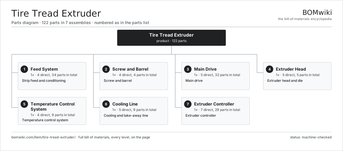
| # | Part | Qty | What it does |
|---|---|---|---|
| 1 | Feed System 4 parts | 1× | Strip feed and conditioning |
| 2 | Screw and Barrel 4 parts | 1× | Screw and barrel |
| 3 | Main Drive 5 parts | 1× | Main drive |
| 4 | Extruder Head 5 parts | 1× | Extruder head and die |
| 5 | Temperature Control System 4 parts | 1× | Temperature control system |
| 6 | Cooling Line 5 parts | 1× | Cooling and take-away line |
| 7 | Extruder Controller 7 parts | 1× | Extruder controller |
3D model
No 3D model yet. Have a CAD file of this? Add a 3D model — STL renders right on this page; STEP, FreeCAD, and OpenSCAD sources are welcome too (openly licensed, like all 3D models on BOMwiki).
Build & assembly graph
expand / collapse · shared sub-assemblies converge · links to related products · est. labourTap an assembly to expand/collapse · tap a part to open it · use “Open page” for any node · drag to pan, scroll to zoom.
Bill of materials for Tire Tread Extruder
7 top-level lines · 52 rows shown · 122 parts total · indented to 3 levels| # | Item / sub-assembly | Part no. | Qty/assy | Ext. qty | Parts | Type |
|---|---|---|---|---|---|---|
| 1 | Feed System 4 parts | tire-tread-extruder-feed | 1× | 1 | 34 | assembly |
| 1.1 | Feed Roller | tire-tread-extruder-feed-roller | 2× | 2 | · | part |
| 1.2 | Warm-up Mill 3 parts | tire-tread-extruder-warmup-mill | 1× | 1 | 7 | assembly |
| 1.2.1 | Mill Roll | tire-tread-extruder-mill-roll | 2× | 2 | · | part |
| 1.2.2 | Ball Bearing | ball-bearing | 4× | 4 | · | part |
| 1.2.3 | Gearbox Housing | gearbox-housing | 1× | 1 | · | part |
| 1.3 | Strip Conveyor | tire-tread-extruder-strip-conveyor | 1× | 1 | · | part |
| 1.4 | Servo Motor 4 parts | servo-motor | 1× | 1 | 24 | assembly |
| 1.4.1 | Stator Assembly 3 parts + deeper › | stator-assembly | 1× | 1 | 3 | assembly |
| 1.4.2 | Rotor Assembly 4 parts + deeper › | rotor-assembly | 1× | 1 | 19 | assembly |
| 1.4.3 | Encoder | encoder | 1× | 1 | · | part |
| 1.4.4 | Motor Housing | motor-housing | 1× | 1 | · | part |
| 2 | Screw and Barrel 4 parts | tire-tread-extruder-screw-barrel | 1× | 1 | 4 | assembly |
| 2.1 | Extruder Screw | tire-tread-extruder-screw | 1× | 1 | · | part |
| 2.2 | Barrel Liner | tire-tread-extruder-barrel | 1× | 1 | · | part |
| 2.3 | Feed Throat | tire-tread-extruder-feed-throat | 1× | 1 | · | part |
| 2.4 | Thrust Bearing | tire-tread-extruder-thrust-bearing | 1× | 1 | · | part |
| 3 | Main Drive 5 parts | tire-tread-extruder-drive | 1× | 1 | 32 | assembly |
| 3.1 | Servo Motor 4 parts | servo-motor | 1× | 1 | 24 | assembly |
| 3.1.1 | Stator Assembly 3 parts + deeper › | stator-assembly | 1× | 1 | 3 | assembly |
| 3.1.2 | Rotor Assembly 4 parts + deeper › | rotor-assembly | 1× | 1 | 19 | assembly |
| 3.1.3 | Encoder | encoder | 1× | 1 | · | part |
| 3.1.4 | Motor Housing | motor-housing | 1× | 1 | · | part |
| 3.2 | Helical Gear Pair | gear-pair | 1× | 1 | · | part |
| 3.3 | Gearbox Housing | gearbox-housing | 1× | 1 | · | part |
| 3.4 | Ball Bearing | ball-bearing | 4× | 4 | · | part |
| 3.5 | Oil Seal | oil-seal | 2× | 2 | · | part |
| 4 | Extruder Head 5 parts | tire-tread-extruder-head | 1× | 1 | 5 | assembly |
| 4.1 | Head Body | tire-tread-extruder-head-body | 1× | 1 | · | part |
| 4.2 | Die Plate | tire-tread-extruder-die-plate | 1× | 1 | · | part |
| 4.3 | Preformer | tire-tread-extruder-preformer | 1× | 1 | · | part |
| 4.4 | Coextrusion Feedblock | tire-tread-extruder-coex-block | 1× | 1 | · | part |
| 4.5 | Breaker Plate | tire-tread-extruder-breaker-plate | 1× | 1 | · | part |
| 5 | Temperature Control System 4 parts | tire-tread-extruder-temperature | 1× | 1 | 9 | assembly |
| 5.1 | Temperature Control Unit | tire-tread-extruder-tcu | 1× | 1 | · | part |
| 5.2 | Water Manifold | tire-tread-extruder-water-manifold | 1× | 1 | · | part |
| 5.3 | Temperature Sensor | tire-tread-extruder-rtd | 6× | 6 | · | part |
| 5.4 | Coolant Pump | coolant-pump | 1× | 1 | · | part |
| 6 | Cooling Line 5 parts | tire-tread-extruder-cooling | 1× | 1 | 9 | assembly |
| 6.1 | Shrinkage Conveyor | tire-tread-extruder-shrink-conveyor | 1× | 1 | · | part |
| 6.2 | Cooling Bath | tire-tread-extruder-cooling-bath | 1× | 1 | · | part |
| 6.3 | Spray Bar | tire-tread-extruder-spray-bar | 4× | 4 | · | part |
| 6.4 | Thickness Gauge | tire-tread-extruder-beta-gauge | 1× | 1 | · | part |
| 6.5 | Drive Belt | drive-belt | 2× | 2 | · | part |
| 7 | Extruder Controller 7 parts | tire-tread-extruder-control | 1× | 1 | 29 | assembly |
| 7.1 | Bare PCB | pcb-bare | 1× | 1 | · | part |
| 7.2 | Microcontroller | mcu | 1× | 1 | · | part |
| 7.3 | Operator Screen | tire-tread-extruder-hmi | 1× | 1 | · | part |
| 7.4 | Power Supply | power-supply | 1× | 1 | · | part |
| 7.5 | Relay | relay | 8× | 8 | · | part |
| 7.6 | Connector | connector | 16× | 16 | · | part |
| 7.7 | Wire Bundle | wire-bundle | 1× | 1 | · | part |
Related products
same domain, ranked by shared parts Foundry Sand Mixer
93 parts · shares 20 with this page
Foundry Sand Mixer
93 parts · shares 20 with this page
 Industrial Parts Washer
423 parts · shares 20 with this page
Powder Coating Line
5,418 parts · shares 20 with this page
Industrial Parts Washer
423 parts · shares 20 with this page
Powder Coating Line
5,418 parts · shares 20 with this page
 Rubber Extrusion Line
524 parts · shares 20 with this page
Acid Pickling Line
1,163 parts · shares 19 with this page
Rubber Extrusion Line
524 parts · shares 20 with this page
Acid Pickling Line
1,163 parts · shares 19 with this page
Sourcing: possible vendors
Prices, MOQ, and lead times are algorithmic estimates, not quotes, and not claims about these companies. Company mappings are curated by keyword; est. price band $5k–$2M. How estimates work| Vendor | HQ | Specialty | MOQ | Lead time |
|---|---|---|---|---|
| atlascopco.com ↗ | Stockholm, SE | Compressors & industrial | 10 units | 12–20 wks |
|
🇦🇹Andritz
andritz.com ↗
|
Graz, AT | Process plants & machinery | 10 units | 12–20 wks |
| buhlergroup.com ↗ | Uzwil, CH | Food & materials processing | 10 units | 12–20 wks |
| gea.com ↗ | Düsseldorf, DE | Process technology | 10 units | 12–20 wks |
| mhi.com ↗ | Tokyo, JP | Heavy machinery | 10 units | 12–20 wks |
955-word article