Plastic Recycling Shredder
ProductOverview
A plastic recycling shredder is the first machine many waste plastics meet in a recycling line. It tears bulky, tough, or contaminated material such as drums, crates, pipe, purge lumps, and baled film into manageable strips and chunks that later machines can wash and granulate. Waste is loaded into the Feed Hopper, where a ram pushes it onto the Twin-Shaft Cutting Unit, two slow counter-rotating shafts of hooked cutters that grab and rip the plastic apart. A Reduction Gearbox supplies the enormous torque, the Drive Motors turns the shafts and works the ram, an optional Discharge Screen limits the output size, and the Control System runs the cycle and reverses on a jam, all mounted on a heavy Frame and Base.
Unlike a granulator, which cuts fast and clean to a precise flake size, a shredder runs slow and brutal, prioritizing torque and the ability to swallow contaminated or oversize material without stalling. The two machines often work in sequence: shred to break things down, then granulate the strips into uniform regrind.
Feeding bulky waste
The Feed Hopper is built large because the feedstock is large. Its tall Hopper Body holds whole drums or crates, and a Pusher Ram driven by a Ram Cylinder sweeps material down against the shafts so they always have something to bite. The ram is needed because light, springy waste like film or hollow parts would otherwise ride on top of the slow shafts without being drawn in. A pair of Ram Guide rails keeps the ram square through its stroke, and the control sequences the ram in step with the shaft load.
The twin-shaft cutting unit
The heart of the machine is the Twin-Shaft Cutting Unit. Two Cutter Shaft members run side by side, each carrying a stack of Cutter Disc cutters separated by Disc Spacer rings, with the discs of one shaft reaching into the gaps of the other. The shafts turn slowly toward each other, and the hooked teeth seize the plastic and pull it down between them, tearing it apart by a combination of cutting and ripping rather than clean shearing. Material that wraps around a shaft is stripped off by a Cleaning Comb. The whole zone is enclosed by the Cutting Housing, and the shafts ride on heavy Ball Bearing units sealed by Oil Seal to keep dust and water out. This geometry is what lets a shredder eat contaminated, gritty, or partly metallic waste that would wreck a fast cutter.
Gearbox and drive
Slow speed and huge force are the signature of this machine, and they come from the Reduction Gearbox. Several Helical Gear Pair reduction stages inside a rigid Gearbox Housing cut motor speed by a large ratio, multiplying torque so the shafts can keep turning through a steel-reinforced hose or a thick HDPE drum without stopping. A Synchronizing Gear set keeps the two shafts meshed in the right phase so their teeth never collide. Power comes from the Drive Motors package: one or two Shaft Drive Motor units connected through a Shaft Coupling, plus a Hydraulic Power Pack that pressurizes the ram. That pack holds a Hydraulic Pump, a Oil Reservoir reservoir, and a Directional Valve that strokes the ram, with a Pressure Sensor watching the system.
Anti-jam control
Because shredders routinely meet pieces they cannot cut, jam handling is built in. The Control System runs the shafts through Variable Frequency Drive drives that watch motor current. When the load spikes, the logic stops the shafts, reverses them to spit the offending piece back up, then drives forward again to retry, repeating a few times before it faults and calls the operator. The Operator Panel shows load, run state, and the cause of any stop. This reverse-on-overload behavior protects the Cutter Disc cutters and the gearbox from the shock of a hard contaminant such as a bolt or a stone.
Sizing and discharge
Many shredders run open and simply drop strips out the bottom, but where a controlled top size matters, the Discharge Screen is fitted. A perforated Screen Plate under the shafts holds material in the cutting zone until pieces are small enough to fall through, and a Screen Frame on a Screen Cylinder swings the screen down for cleaning and inspection. Output drops by gravity onto a conveyor or into a bin and usually moves on to washing or to a granulator for finer reduction.
Materials and use
Recycling shredders handle the full range of post-consumer and post-industrial plastics: HDPE drums and crates, PP, rigid PVC pipe, polystyrene, baled film, and mixed plastic from material recovery facilities. They tolerate the dirt, grit, and occasional metal that come with real waste, which is why they lead nearly every plastics recycling line. Their limits are throughput and output precision, since the slow shafts move less material per hour than a fast granulator and leave coarse, uneven pieces. The standard line answer is to shred first for capacity and contaminant tolerance, then granulate the strips into the uniform regrind that washing and pelletizing need. The main wear items are the Cutter Disc cutters, which are rotated and reground or replaced as the hooks dull.
Plastic Recycling Shredder parts and their functions
7 top-level parts · 169 parts in total · full bill of materials below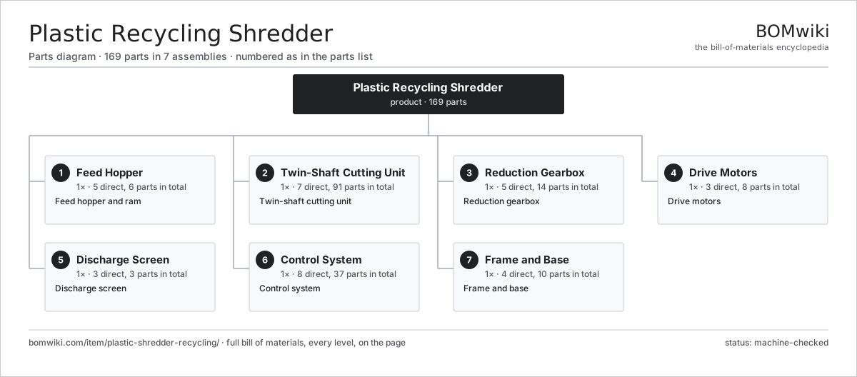
| # | Part | Qty | What it does |
|---|---|---|---|
| 1 | Feed Hopper 5 parts | 1× | Feed hopper and ram |
| 2 | Twin-Shaft Cutting Unit 7 parts | 1× | Twin-shaft cutting unit |
| 3 | Reduction Gearbox 5 parts | 1× | Reduction gearbox |
| 4 | Drive Motors 3 parts | 1× | Drive motors |
| 5 | Discharge Screen 3 parts | 1× | Discharge screen |
| 6 | Control System 8 parts | 1× | Control system |
| 7 | Frame and Base 4 parts | 1× | Frame and base |
3D model
No 3D model yet. Have a CAD file of this? Add a 3D model — STL renders right on this page; STEP, FreeCAD, and OpenSCAD sources are welcome too (openly licensed, like all 3D models on BOMwiki).
Build & assembly graph
expand / collapse · shared sub-assemblies converge · links to related products · est. labourTap an assembly to expand/collapse · tap a part to open it · use “Open page” for any node · drag to pan, scroll to zoom.
Bill of materials for Plastic Recycling Shredder
7 top-level lines · 46 rows shown · 169 parts total · indented to 3 levels| # | Item / sub-assembly | Part no. | Qty/assy | Ext. qty | Parts | Type |
|---|---|---|---|---|---|---|
| 1 | Feed Hopper 5 parts | plastic-shredder-recycling-hopper | 1× | 1 | 6 | assembly |
| 1.1 | Hopper Body | plastic-shredder-recycling-hopper-body | 1× | 1 | · | part |
| 1.2 | Pusher Ram | plastic-shredder-recycling-ram | 1× | 1 | · | part |
| 1.3 | Ram Cylinder | plastic-shredder-recycling-ram-cylinder | 1× | 1 | · | part |
| 1.4 | Ram Guide | plastic-shredder-recycling-ram-guide | 2× | 2 | · | part |
| 1.5 | Fastener Set | fastener-set | 1× | 1 | · | part |
| 2 | Twin-Shaft Cutting Unit 7 parts | plastic-shredder-recycling-cutting-unit | 1× | 1 | 91 | assembly |
| 2.1 | Cutter Shaft | plastic-shredder-recycling-cutter-shaft | 2× | 2 | · | part |
| 2.2 | Cutter Disc | plastic-shredder-recycling-cutter-disc | 40× | 40 | · | part |
| 2.3 | Disc Spacer | plastic-shredder-recycling-spacer | 38× | 38 | · | part |
| 2.4 | Cleaning Comb | plastic-shredder-recycling-cleaning-comb | 2× | 2 | · | part |
| 2.5 | Ball Bearing | ball-bearing | 4× | 4 | · | part |
| 2.6 | Oil Seal | oil-seal | 4× | 4 | · | part |
| 2.7 | Cutting Housing | plastic-shredder-recycling-cutter-housing | 1× | 1 | · | part |
| 3 | Reduction Gearbox 5 parts | plastic-shredder-recycling-gearbox | 1× | 1 | 14 | assembly |
| 3.1 | Helical Gear Pair | gear-pair | 3× | 3 | · | part |
| 3.2 | Gearbox Housing | gearbox-housing | 1× | 1 | · | part |
| 3.3 | Ball Bearing | ball-bearing | 6× | 6 | · | part |
| 3.4 | Oil Seal | oil-seal | 2× | 2 | · | part |
| 3.5 | Synchronizing Gear | plastic-shredder-recycling-sync-gear | 2× | 2 | · | part |
| 4 | Drive Motors 3 parts | plastic-shredder-recycling-drive | 1× | 1 | 8 | assembly |
| 4.1 | Shaft Drive Motor | plastic-shredder-recycling-shaft-motor | 2× | 2 | · | part |
| 4.2 | Hydraulic Power Pack 4 parts | plastic-shredder-recycling-hydraulic-pack | 1× | 1 | 4 | assembly |
| 4.2.1 | Hydraulic Pump | plastic-shredder-recycling-hyd-pump | 1× | 1 | · | part |
| 4.2.2 | Oil Reservoir | plastic-shredder-recycling-hyd-tank | 1× | 1 | · | part |
| 4.2.3 | Directional Valve | plastic-shredder-recycling-hyd-valve | 1× | 1 | · | part |
| 4.2.4 | Pressure Sensor | pressure-sensor | 1× | 1 | · | part |
| 4.3 | Shaft Coupling | plastic-shredder-recycling-coupling | 2× | 2 | · | part |
| 5 | Discharge Screen 3 parts | plastic-shredder-recycling-screen | 1× | 1 | 3 | assembly |
| 5.1 | Screen Plate | plastic-shredder-recycling-screen-plate | 1× | 1 | · | part |
| 5.2 | Screen Frame | plastic-shredder-recycling-screen-frame | 1× | 1 | · | part |
| 5.3 | Screen Cylinder | plastic-shredder-recycling-screen-cylinder | 1× | 1 | · | part |
| 6 | Control System 8 parts | plastic-shredder-recycling-control | 1× | 1 | 37 | assembly |
| 6.1 | Bare PCB | pcb-bare | 1× | 1 | · | part |
| 6.2 | Microcontroller | mcu | 1× | 1 | · | part |
| 6.3 | Variable Frequency Drive | plastic-shredder-recycling-vfd | 2× | 2 | · | part |
| 6.4 | Operator Panel | plastic-shredder-recycling-hmi | 1× | 1 | · | part |
| 6.5 | Relay | relay | 6× | 6 | · | part |
| 6.6 | Power Supply | power-supply | 1× | 1 | · | part |
| 6.7 | Connector | connector | 24× | 24 | · | part |
| 6.8 | Wire Bundle | wire-bundle | 1× | 1 | · | part |
| 7 | Frame and Base 4 parts | plastic-shredder-recycling-frame | 1× | 1 | 10 | assembly |
| 7.1 | Base Frame | plastic-shredder-recycling-base-frame | 1× | 1 | · | part |
| 7.2 | Sheet Metal Panel | sheet-panel | 4× | 4 | · | part |
| 7.3 | Anchor Foot | plastic-shredder-recycling-anchor-foot | 4× | 4 | · | part |
| 7.4 | Fastener Set | fastener-set | 1× | 1 | · | part |
Related products
same domain, ranked by shared parts Industrial Parts Washer
423 parts · shares 10 with this page
Powder Coating Line
5,418 parts · shares 10 with this page
Blown Film Extrusion Line
436 parts · shares 9 with this page
Cast Film Extrusion Line
406 parts · shares 9 with this page
Industrial Parts Washer
423 parts · shares 10 with this page
Powder Coating Line
5,418 parts · shares 10 with this page
Blown Film Extrusion Line
436 parts · shares 9 with this page
Cast Film Extrusion Line
406 parts · shares 9 with this page
Sourcing: possible vendors
Prices, MOQ, and lead times are algorithmic estimates, not quotes, and not claims about these companies. Company mappings are curated by keyword; est. price band $5k–$2M. How estimates work| Vendor | HQ | Specialty | MOQ | Lead time |
|---|---|---|---|---|
| atlascopco.com ↗ | Stockholm, SE | Compressors & industrial | 10 units | 12–20 wks |
|
🇦🇹Andritz
andritz.com ↗
|
Graz, AT | Process plants & machinery | 10 units | 12–20 wks |
| buhlergroup.com ↗ | Uzwil, CH | Food & materials processing | 10 units | 12–20 wks |
| gea.com ↗ | Düsseldorf, DE | Process technology | 10 units | 12–20 wks |
| mhi.com ↗ | Tokyo, JP | Heavy machinery | 10 units | 12–20 wks |
950-word article